
Flow Air In Pipes Calculator

The Flow Air In Pipes Calculator is a valuable tool for engineers and technicians who need to calculate the flow rate of air in pipes. This calculator takes into account various factors such as pipe diameter, length, and air pressure to provide accurate results. With its user-friendly interface, users can easily input values and obtain the desired flow rate. The calculator is particularly useful in industries such as HVAC, aerospace, and chemical processing, where precise air flow calculations are crucial for system design and optimization. Accurate calculations ensure efficient system performance and safety.
Flow Air In Pipes Calculator: A Comprehensive Guide
The Flow Air In Pipes Calculator is a valuable tool used to calculate the flow rate of air in pipes, which is essential in various industries such as HVAC, chemical processing, and power generation. This calculator takes into account several factors, including the pipe's diameter, length, and material, as well as the air's temperature, pressure, and velocity. By using this calculator, engineers and technicians can design and optimize pipe systems to ensure efficient and safe air flow.
Introduction to Flow Air In Pipes Calculator
The Flow Air In Pipes Calculator is based on the principles of fluid dynamics and thermodynamics. It uses equations such as the Darcy-Weisbach equation and the Colebrook-White equation to calculate the friction factor and pressure drop in the pipe. The calculator also considers the viscosity and density of the air, as well as the roughness of the pipe's surface.
Key Factors Affects Flow Air In Pipes
Several factors can affect the flow rate of air in pipes, including:
| Factor | Description |
|---|---|
| Pipe Diameter | The diameter of the pipe, which affects the flow area and friction factor |
| Pipe Length | The length of the pipe, which affects the pressure drop and flow rate |
| Air Temperature | The temperature of the air, which affects the viscosity and density |
| Air Pressure | The pressure of the air, which affects the flow rate and pressure drop |
| Pipe Material | The material of the pipe, which affects the roughness and friction factor |
Applications of Flow Air In Pipes Calculator
The Flow Air In Pipes Calculator has various applications in industries such as:
HVAC (Heating, Ventilation, and Air Conditioning)
Chemical processing
Power generation
Aerospace engineering
Automotive engineering
Benefits of Using Flow Air In Pipes Calculator
Using the Flow Air In Pipes Calculator can provide several benefits, including:
Improved accuracy in calculating flow rates and pressure drops
Increased efficiency in designing and optimizing pipe systems
Reduced costs by minimizing energy losses and pipeline failures
Enhanced safety by ensuring safe operating pressures and flow rates
Limitations and Assumptions of Flow Air In Pipes Calculator
The Flow Air In Pipes Calculator has some limitations and assumptions, including:
Assuming steady-state flow
Neglecting heat transfer and condensation effects
Using simplified equations and empirical correlations
Ignoring pipe fittings and valves effects on flow rate and pressure drop
How to calculate the flow rate of air in a pipe?
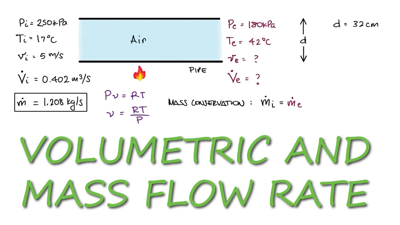
To calculate the flow rate of air in a pipe, you need to know the velocity of the air and the cross-sectional area of the pipe. The flow rate can be calculated using the formula: Q = A x V, where Q is the flow rate, A is the cross-sectional area, and V is the velocity. The velocity of the air can be measured using an anemometer or calculated using the Bernoulli's principle. The cross-sectional area of the pipe can be calculated using the formula: A = π x (d/2)^2, where d is the diameter of the pipe.
Understanding the Formula for Flow Rate Calculation
The formula for calculating the flow rate of air in a pipe is based on the principle of conservation of mass, which states that the mass flow rate of a fluid remains constant throughout a pipe. To calculate the flow rate, you need to know the following parameters:
- Diameter of the pipe: The diameter of the pipe is used to calculate the cross-sectional area.
- Velocity of the air: The velocity of the air can be measured using an anemometer or calculated using the Bernoulli's principle.
- Density of the air: The density of the air is used to calculate the mass flow rate.
The formula for calculating the flow rate is Q = A x V, where Q is the flow rate, A is the cross-sectional area, and V is the velocity.
Measuring the Velocity of Air in a Pipe
Measuring the velocity of air in a pipe is crucial for calculating the flow rate. There are several methods to measure the velocity of air, including using an anemometer, pitot tube, or hot wire anemometer. The choice of method depends on the accuracy required and the complexity of the measurement.
- Anemometer: An anemometer is a device that measures the velocity of air using a rotating cups or vanes.
- Pitot tube: A pitot tube is a device that measures the velocity of air using the pressure difference between the stagnation point and the free stream.
- Hot wire anemometer: A hot wire anemometer is a device that measures the velocity of air using the heat transfer from a hot wire to the surrounding air.
The velocity of the air can be measured at different points in the pipe to ensure accurate results.
Calculating the Cross-Sectional Area of a Pipe
The cross-sectional area of a pipe is used to calculate the flow rate of air. The cross-sectional area can be calculated using the formula: A = π x (d/2)^2, where d is the diameter of the pipe.
- Diameter of the pipe: The diameter of the pipe is used to calculate the cross-sectional area.
- Shape of the pipe: The shape of the pipe can affect the cross-sectional area, with circular pipes having a constant cross-sectional area and rectangular pipes having a variable cross-sectional area.
- Obstructions in the pipe: Obstructions in the pipe, such as valves or fittings, can affect the cross-sectional area and the flow rate.
The cross-sectional area of the pipe is an important parameter in calculating the flow rate of air.
Factors Affecting the Flow Rate of Air in a Pipe
There are several factors that can affect the flow rate of air in a pipe, including the velocity of the air, the cross-sectional area of the pipe, and the density of the air.
- Friction in the pipe: Friction in the pipe can reduce the flow rate of air by converting some of the kinetic energy into heat.
- Turbulence in the pipe: Turbulence in the pipe can increase the flow rate of air by mixing the air and reducing the boundary layer.
- Leaks in the pipe: Leaks in the pipe can reduce the flow rate of air by allowing some of the air to escape.
The flow rate of air in a pipe can be affected by several factors, including the velocity, cross-sectional area, and density of the air.
Applications of Flow Rate Calculation in Piping Systems
Calculating the flow rate of air in a pipe is an important aspect of piping system design and operation. The flow rate can be used to size pipes, select equipment, and optimize system performance.
- Heating, Ventilation, and Air Conditioning (HVAC) systems: The flow rate of air is used to design and operate HVAC systems, including air handlers, ducts, and ventilation systems.
- Industrial processes: The flow rate of air is used in industrial processes, such as pneumatic conveying, air pollution control, and chemical processing.
- Aerospace applications: The flow rate of air is used in aerospace applications, such as aircraft engines, missile systems, and spacecraft propulsion systems.
The flow rate of air in a pipe is a critical parameter in various applications, including piping system design, industrial processes, and aerospace applications.
How do you measure air flow in a pipe?
To measure air flow in a pipe, you need to use specialized equipment and techniques. The most common method is to use an anemometer, which is a device that measures the velocity of air in a pipeline. Another method is to use a pilot tube, which measures the pressure difference between two points in the pipe, allowing you to calculate the air flow rate.
Types of Air Flow Measurement Devices
There are several types of devices that can be used to measure air flow in a pipe, including hot wire anemometers, vortex flow meters, and ultrasonic flow meters. These devices use different technologies to measure air flow, such as detecting changes in temperature, pressure, or ultrasonic signals. Some of the key features to consider when selecting an air flow measurement device include:
- Accuracy: The device should be able to provide accurate measurements of air flow rate.
- Reliability: The device should be able to withstand the conditions in the pipe, such as temperature and pressure fluctuations.
- Ease of use: The device should be easy to install, calibrate, and operate.
Calibration and Installation of Air Flow Meters
Calibration and installation of air flow meters are critical steps to ensure accurate measurements. The device should be calibrated according to the manufacturer's instructions and installed in a location where it can provide a representative measurement of the air flow in the pipe. Some of the key considerations when installing an air flow meter include:
- Pipe size and shape: The device should be compatible with the pipe size and shape.
- Flow profile: The device should be installed in a location where the flow profile is representative of the average flow in the pipe.
- Interference: The device should be installed in a location where it is not subject to interference from other equipment or sources.
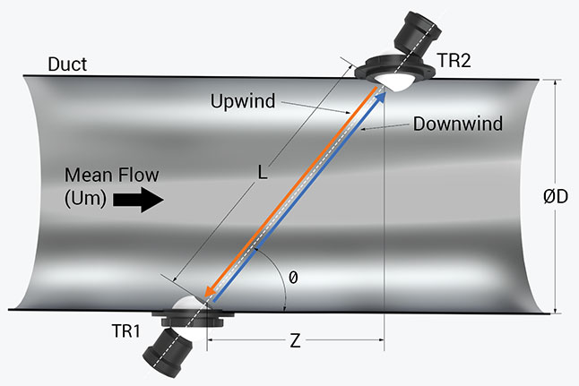
Air Flow Measurement Techniques
There are several techniques that can be used to measure air flow in a pipe, including traverse measurement, orifice plate measurement, and venturi tube measurement. These techniques use different methods to measure air flow, such as detecting changes in pressure or velocity. Some of the key advantages and disadvantages of each technique include:
- Traverse measurement: This technique provides a highly accurate measurement of air flow, but it can be time-consuming and expensive to implement.
- Orifice plate measurement: This technique is relatively simple and inexpensive to implement, but it can be less accurate than other methods.
- Venturi tube measurement: This technique provides a high degree of accuracy and is relatively easy to implement, but it can be more expensive than other methods.
Applications of Air Flow Measurement in Pipes
Air flow measurement in pipes has a wide range of applications, including industrial process control, heating, ventilation, and air conditioning (HVAC), and environmental monitoring. In these applications, accurate measurement of air flow is critical to ensuring efficient operation, energy savings, and compliance with regulations. Some of the key benefits of air flow measurement in these applications include:
- Improved process control: Accurate measurement of air flow allows for more precise control of industrial processes.
- Energy savings: Optimizing air flow can help reduce energy consumption and costs.
- Regulatory compliance: Accurate measurement of air flow is often required to comply with environmental regulations.
Challenges and Limitations of Air Flow Measurement in Pipes
There are several challenges and limitations to measuring air flow in pipes, including pipe size and shape, flow profile, and interference. These factors can affect the accuracy and reliability of air flow measurements, and must be carefully considered when selecting and installing an air flow measurement device. Some of the key strategies for overcoming these challenges include:
- Using calibrated devices: Ensuring that the device is properly calibrated can help minimize errors.
- Selecting the right technology: Choosing a device that is compatible with the pipe size and shape, and the flow profile, can help ensure accurate measurements.
- Implementing data validation: Verifying the accuracy of the measurements can help identify and correct errors.
How do you calculate the volume of air in a pipe?

To calculate the volume of air in a pipe, you need to know the length, diameter, and temperature of the pipe, as well as the air pressure inside it. The volume of air can be calculated using the ideal gas law, which states that pressure (P), volume (V), and temperature (T) are related by the equation PV = nRT, where n is the number of moles of gas and R is the gas constant.
Understanding the Formula
The formula for calculating the volume of air in a pipe is based on the ideal gas law, which assumes that the gas behaves ideally. To apply this formula, you need to know the length and diameter of the pipe, as well as the temperature and pressure of the air inside it. The calculation involves the following steps:
- Determine the cross-sectional area of the pipe using the formula A = πd^2/4, where d is the diameter of the pipe.
- Calculate the volume of the pipe using the formula V = A L, where L is the length of the pipe.
- Apply the ideal gas law to calculate the volume of air in the pipe, using the known values of pressure, temperature, and volume.
Factors Affecting Volume Calculation
Several factors can affect the accuracy of the volume calculation, including pipe roughness, bends, and fittings, which can cause turbulence and pressure drops. Additionally, temperature variations and humidity can also impact the calculation. To ensure accurate results, it is essential to consider these factors and use correction factors or empirical equations to account for their effects. The calculation may involve the following considerations:
- Viscosity of the air, which can affect the flow rate and pressure drop in the pipe.
- Compressibility of the air, which can affect the volume and pressure inside the pipe.
- Heat transfer between the air and the pipe, which can affect the temperature and pressure of the air.
Measuring Air Pressure and Temperature
To calculate the volume of air in a pipe, you need to measure the air pressure and temperature inside the pipe. This can be done using pressure sensors and thermometers, which provide accurate and reliable readings. The measurement process may involve the following steps:
- Installing pressure sensors and thermometers at strategic locations along the pipe.
- Calibrating the sensors and thermometers to ensure accurate readings.
- Recording the pressure and temperature data over a period of time to account for fluctuations and variations.
Applications of Volume Calculation
Calculating the volume of air in a pipe has several practical applications, including pneumatic systems, HVAC systems, and industrial processes. Accurate volume calculations are essential for designing and optimizing these systems, ensuring efficient operation, reliable performance, and safe operation. The applications may involve the following:
- System design, where accurate volume calculations are used to determine pipe sizes, valve sizes, and compressor capacities.
- System optimization, where volume calculations are used to fine-tune system performance, reduce energy consumption, and minimize costs.
- Troubleshooting, where volume calculations are used to diagnose problems, identify bottlenecks, and develop solutions.
Common Challenges and Limitations
Calculating the volume of air in a pipe can be challenging due to various limitations and uncertainties, including pipe geometry, air properties, and measurement errors. To overcome these challenges, it is essential to use accurate models, reliable data, and robust calculation methods, such as computational fluid dynamics (CFD) and finite element analysis (FEA). The challenges may involve the following:
- Complex pipe geometries, which can make it difficult to accurately calculate the volume and flow rate of air.
- Unknown air properties, such as viscosity and density, which can affect the accuracy of the calculation.
- Measurement uncertainties, which can introduce errors and inaccuracies into the calculation.
How to calculate CFM in a pipe?
To calculate CFM (cubic feet per minute) in a pipe, you need to know the flow rate of the fluid, the pipe diameter, and the velocity of the fluid. The formula to calculate CFM is: CFM = (π × (diameter/2)^2) × velocity. Where π is a constant approximately equal to 3.14, diameter is the pipe diameter in feet, and velocity is the velocity of the fluid in feet per minute.
Understanding the Formula
To calculate CFM, you need to understand the formula and the variables involved. The formula takes into account the cross-sectional area of the pipe and the velocity of the fluid. The cross-sectional area is calculated using the pipe diameter, which is a critical factor in determining the flow rate. Here are the steps to calculate CFM:
- Measure the pipe diameter in feet
- Calculate the cross-sectional area using the formula: area = π × (diameter/2)^2
- Measure the velocity of the fluid in feet per minute
Measuring Flow Rate
Measuring the flow rate is crucial in calculating CFM. The flow rate can be measured using various methods, including orifice plates, venturi tubes, and pilot tubes. These methods measure the pressure drop across the pipe, which is then used to calculate the flow rate. Here are some common methods to measure flow rate:
- Orifice plates: measure the pressure drop across a restricted area in the pipe
- Venturi tubes: measure the pressure drop across a constricted section of the pipe
- Pilot tubes: measure the velocity of the fluid at a specific point in the pipe
Calculating Velocity
Calculating the velocity of the fluid is essential in determining CFM. The velocity can be calculated using the flow rate and the cross-sectional area of the pipe. Here are the steps to calculate velocity:
- Measure the flow rate in cubic feet per minute
- Calculate the cross-sectional area using the pipe diameter
- Calculate the velocity using the formula: velocity = flow rate / cross-sectional area
Factors Affecting CFM
Several factors can affect CFM, including pipe size, pipe material, and fluid properties. The pipe size and pipe material can affect the friction and pressure drop in the pipe, which can impact CFM. The fluid properties, such as density and viscosity, can also affect the flow rate and velocity. Here are some factors that can affect CFM:
- Pipe size: larger pipes can increase CFM, while smaller pipes can decrease CFM
- Pipe material: smooth pipes can increase CFM, while rough pipes can decrease CFM
- Fluid properties: changes in density and viscosity can affect the flow rate and velocity
Applications of CFM Calculation
Calculating CFM has various applications in different fields, including HVAC, plumbing, and industrial processes. In HVAC, CFM is used to calculate the air flow rate in ducts and vents. In plumbing, CFM is used to calculate the water flow rate in pipes. Here are some applications of CFM calculation:
- HVAC: calculating air flow rate in ducts and vents
- Plumbing: calculating water flow rate in pipes
- Industrial processes: calculating fluid flow rate in pipes and equipment
Frequently Asked Questions (FAQs)
What is the Flow Air In Pipes Calculator and how does it work?
The Flow Air In Pipes Calculator is an online tool designed to calculate the flow rate of air in pipes, taking into account various factors such as pipe diameter, air pressure, and temperature. This calculator uses complex algorithms and formulas to provide accurate calculations, making it a valuable resource for engineers, technicians, and researchers working in fields such as mechanical engineering, aerospace engineering, and chemical engineering. The calculator's primary function is to determine the mass flow rate of air in a pipe, which is essential for designing and optimizing pneumatic systems, air conditioning systems, and ventilation systems. By inputting the necessary parameters, users can obtain precise calculations, which can help them identify potential bottlenecks and inefficiencies in their systems.
What are the key parameters required to use the Flow Air In Pipes Calculator?
To use the Flow Air In Pipes Calculator, users need to input several key parameters, including pipe diameter, pipe length, air pressure, temperature, and relative humidity. The pipe diameter is a critical parameter, as it affects the flow rate and pressure drop of the air in the pipe. The air pressure and temperature are also essential, as they influence the density and viscosity of the air, which in turn impact the flow rate. Additionally, the relative humidity is important, as it can affect the air density and flow characteristics. By providing these parameters, users can ensure that the calculator provides accurate and reliable results, which can be used to design, optimize, and troubleshoot their pneumatic systems and airflow applications.
How can the Flow Air In Pipes Calculator be used in real-world applications?
The Flow Air In Pipes Calculator has a wide range of real-world applications, including heating, ventilation, and air conditioning (HVAC) systems, pneumatic conveying systems, air compression systems, and aerospace engineering. In HVAC systems, the calculator can be used to determine the flow rate of air in ducts and pipes, which is essential for ensuring efficient and effective heating and cooling. In pneumatic conveying systems, the calculator can be used to optimize the flow rate of air and particle velocity, which is critical for transporting and handling bulk materials. In air compression systems, the calculator can be used to determine the flow rate of air and pressure ratios, which is essential for designing and optimizing air compressors and pneumatic systems.
What are the limitations and assumptions of the Flow Air In Pipes Calculator?
The Flow Air In Pipes Calculator is based on several assumptions and limitations, which users should be aware of when using the tool. One of the primary assumptions is that the air is ideal and incompressible, which may not be true in all real-world applications. Additionally, the calculator assumes that the pipe is straight and horizontal, which may not be the case in complex piping systems. The calculator also assumes that the air flow is laminar and turbulent, which may not be accurate in all flow regimes. Furthermore, the calculator does not account for heat transfer, friction, and other losses, which can affect the accuracy of the results. By understanding these limitations and assumptions, users can use the calculator effectively and make informed decisions about their pneumatic systems and airflow applications.
Deja una respuesta
Entradas Relacionadas