
Discharge of Air Through An Orifice Equation and Calculator
The discharge of air through an orifice is a fundamental concept in fluid mechanics, crucial for understanding various industrial and engineering applications. The equation governing this phenomenon is based on the principle of conservation of mass and energy, taking into account factors such as pressure, temperature, and orifice geometry. This article provides an overview of the discharge of air through an orifice equation and offers a calculator to simplify the calculation process, enabling engineers and researchers to accurately determine airflow rates and pressures in various systems and applications. The equation is widely used in engineering design.
- Discharge of Air Through An Orifice Equation and Calculator
- What is the pressure drop of air through an orifice?
- What is the equation for drainage orifice?
- What is the discharge coefficient of air orifice?
-
Frequently Asked Questions (FAQs)
- What is the Discharge of Air Through An Orifice Equation and Calculator?
- How does the Discharge of Air Through An Orifice Equation and Calculator work?
- What are the limitations and assumptions of the Discharge of Air Through An Orifice Equation and Calculator?
- How can the Discharge of Air Through An Orifice Equation and Calculator be applied in real-world applications?
Discharge of Air Through An Orifice Equation and Calculator
The discharge of air through an orifice is a fundamental concept in fluid dynamics, and it is crucial in designing and optimizing various systems, such as ventilation systems, pneumatic systems, and aircraft engines. The equation for the discharge of air through an orifice is based on the ideal gas law and the equation of state for a compressible fluid. The equation is given by: Q = A sqrt(2 ΔP / ρ), where Q is the volumetric flow rate, A is the cross-sectional area of the orifice, ΔP is the pressure difference across the orifice, and ρ is the density of the air.
Introduction to Orifice Flow
The flow of air through an orifice is a complex phenomenon that involves the interaction of various physical parameters, such as pressure, temperature, and velocity. The orifice can be either subsonic or supersonic, depending on the Mach number of the flow. The orifice equation is a simplified model that assumes a one-dimensional flow and neglects the effects of viscosity and turbulence.
Derivation of the Orifice Equation
The derivation of the orifice equation involves the application of the conservation of mass and conservation of energy principles. The equation is derived by integrating the Navier-Stokes equations across the orifice, assuming a steady-state flow and a uniform velocity profile. The resulting equation is a function of the orifice area, pressure difference, and air density.
Applications of the Orifice Equation
The orifice equation has numerous applications in various fields, including aerospace engineering, chemical engineering, and mechanical engineering. It is used to design and optimize aircraft engines, ventilation systems, and pneumatic systems. The equation is also used to predict the flow rate and pressure drop across an orifice, which is essential in designing and operating industrial processes.
Limitations of the Orifice Equation
The orifice equation has several limitations, including the assumption of a one-dimensional flow and the neglect of viscosity and turbulence effects. The equation is also sensitive to the orifice geometry and the flow regime. In addition, the equation does not account for the effects of heat transfer and condensation, which can be significant in certain applications.
Orifice Flow Calculator
An orifice flow calculator is a tool used to calculate the flow rate and pressure drop across an orifice. The calculator uses the orifice equation and requires input parameters such as the orifice area, pressure difference, and air density. The calculator can be used to design and optimize orifice-based systems, such as ventilation systems and pneumatic systems.
| Parameter | Units | Description |
|---|---|---|
| Q | m3/s | Volumetric flow rate |
| A | m2 | Cross-sectional area of the orifice |
| ΔP | Pascal | Pressure difference across the orifice |
| ρ | kg/m3 | Density of the air |
What is the pressure drop of air through an orifice?

The pressure drop of air through an orifice is a complex phenomenon that depends on several factors, including the size and shape of the orifice, the velocity of the air, and the density of the air. The pressure drop can be calculated using various equations, such as the Bernoulli's equation, which relates the pressure and velocity of a fluid (in this case, air) as it flows through a constricted section.
Factors Affecting Pressure Drop
The pressure drop of air through an orifice is affected by several factors, including:
- The size of the orifice, which can affect the flow rate and pressure drop of the air.
- The shape of the orifice, which can affect the flow pattern and turbulence of the air.
- The velocity of the air, which can affect the pressure drop and flow rate of the air.
These factors can interact with each other in complex ways, making it challenging to predict the pressure drop of air through an orifice.
Calculating Pressure Drop
Calculating the pressure drop of air through an orifice can be done using various equations, including:
- The Bernoulli's equation, which relates the pressure and velocity of a fluid (in this case, air) as it flows through a constricted section.
- The Darcy-Weisbach equation, which relates the pressure drop and flow rate of a fluid (in this case, air) as it flows through a pipe or orifice.
- The orifice equation, which relates the pressure drop and flow rate of a fluid (in this case, air) as it flows through an orifice.
These equations can be used to calculate the pressure drop of air through an orifice, but they require accurate measurements of the flow rate and velocity of the air.
Types of Orifices
There are several types of orifices that can be used to control the flow of air, including:
- Sharp-edged orifices, which have a sharp edge and a small diameter.
- Round-edged orifices, which have a rounded edge and a larger diameter.
- Conical orifices, which have a conical shape and a variable diameter.
Each type of orifice has its own unique characteristics and can be used in different applications to control the flow of air.
Applications of Orifices
Orifices are used in a variety of applications, including:
- Aerospace engineering, where orifices are used to control the flow of air and fuel in jet engines.
- Chemical engineering, where orifices are used to control the flow of fluids and gases in chemical reactors.
- Biomedical engineering, where orifices are used to control the flow of air and fluids in medical devices.
In these applications, orifices are used to control the flow of fluids and gases, and to regulate the pressure and flow rate.
Challenges and Limitations
There are several challenges and limitations associated with using orifices to control the flow of air, including:
- The complexity of the flow patterns and turbulence that can occur in orifices.
- The difficulty of predicting the pressure drop and flow rate of air through an orifice.
- The sensitivity of orifices to manufacturing errors and wear and tear.
These challenges and limitations can make it difficult to design and optimize orifices for specific applications, and require careful consideration of the design parameters and operating conditions.
What is the equation for drainage orifice?
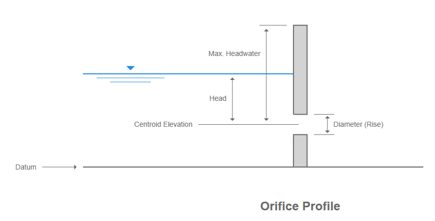
The equation for drainage orifice is based on the Torricelli's theorem, which states that the velocity of a fluid flowing through an orifice is proportional to the square root of the height of the fluid above the orifice. The equation is given by: Q = A √(2 g h), where Q is the discharge rate, A is the cross-sectional area of the orifice, g is the acceleration due to gravity, and h is the height of the fluid above the orifice.
Understanding the Variables
The variables in the equation for drainage orifice are crucial in determining the discharge rate. The cross-sectional area of the orifice (A) is the area through which the fluid flows, and it is typically measured in units of square meters. The acceleration due to gravity (g) is a constant that is approximately equal to 9.81 meters per second squared. The height of the fluid above the orifice (h) is the distance between the surface of the fluid and the orifice, and it is typically measured in units of meters.
- The cross-sectional area of the orifice (A) affects the discharge rate directly, as a larger area results in a higher discharge rate.
- The acceleration due to gravity (g) affects the discharge rate indirectly, as it is a constant that is used to calculate the velocity of the fluid.
- The height of the fluid above the orifice (h) affects the discharge rate directly, as a greater height results in a higher velocity and therefore a higher discharge rate.
Factors Affecting the Equation
There are several factors that can affect the equation for drainage orifice, including the viscosity of the fluid, the surface tension of the fluid, and the roughness of the orifice. The viscosity of the fluid can affect the discharge rate, as a more viscous fluid will have a lower discharge rate. The surface tension of the fluid can also affect the discharge rate, as a fluid with a higher surface tension will have a lower discharge rate. The roughness of the orifice can also affect the discharge rate, as a smoother orifice will result in a higher discharge rate.
- The viscosity of the fluid can be affected by the temperature and pressure of the fluid.
- The surface tension of the fluid can be affected by the composition of the fluid and the presence of surfactants.
- The roughness of the orifice can be affected by the material and manufacturing process used to create the orifice.
Applications of the Equation
The equation for drainage orifice has several practical applications, including the design of drainage systems, the calculation of flood risk, and the optimization of water treatment processes. The equation can be used to calculate the discharge rate of a fluid through an orifice, which is essential in the design of drainage systems. The equation can also be used to calculate the flood risk of an area, by determining the discharge rate of a fluid through an orifice and comparing it to the capacity of the drainage system.
- The equation can be used to design drainage systems that can handle heavy rainfall or flooding.
- The equation can be used to calculate the flood risk of an area and determine the necessary measures to mitigate the risk.
- The equation can be used to optimize water treatment processes, by determining the discharge rate of a fluid through an orifice and adjusting the treatment process accordingly.
Limitations of the Equation
The equation for drainage orifice has several limitations, including the assumption of a steady-state flow, the assumption of a incompressible fluid, and the neglect of frictional losses. The equation assumes that the flow is steady-state, which means that the discharge rate is constant over time. The equation also assumes that the fluid is incompressible, which means that the density of the fluid is constant. The equation neglects frictional losses, which can occur due to the roughness of the orifice or the viscosity of the fluid.
- The equation assumes a steady-state flow, which may not be the case in real-world applications.
- The equation assumes an incompressible fluid, which may not be the case for gases or compressible liquids.
- The equation neglects frictional losses, which can result in a lower discharge rate than predicted.
Future Developments
There are several future developments that can be made to the equation for drainage orifice, including the development of more accurate models that take into account frictional losses and non-steady-state flow. The development of more accurate models can be achieved through experimental research and numerical simulations. The use of computational fluid dynamics (CFD) can also be used to simulate the flow of a fluid through an orifice and determine the discharge rate.
- The development of more accurate models can be achieved through experimental research and numerical simulations.
- The use of computational fluid dynamics (CFD) can be used to simulate the flow of a fluid through an orifice and determine the discharge rate.
- The development of new materials and manufacturing processes can be used to create more efficient orifices that result in a higher discharge rate.
What is the discharge coefficient of air orifice?
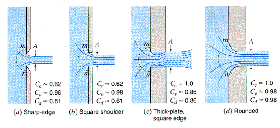
The discharge coefficient of an air orifice is a measure of the efficiency with which air flows through the orifice. It is defined as the ratio of the actual flow rate to the theoretical flow rate, and it is typically denoted by the letter C. The discharge coefficient is an important parameter in the design and operation of air orifices, as it determines the amount of air that can flow through the orifice for a given pressure drop.
Introduction to Discharge Coefficient
The discharge coefficient is a critical parameter in the design and operation of air orifices. It is influenced by several factors, including the shape and size of the orifice, the Reynolds number, and the Mach number. The discharge coefficient is typically measured experimentally, and it can be affected by factors such as turbulence, boundary layers, and viscous effects. Some key factors that influence the discharge coefficient include:
- Orifice shape and size: The shape and size of the orifice can significantly affect the discharge coefficient.
- Reynolds number: The Reynolds number is a measure of the ratio of inertial forces to viscous forces, and it can have a significant impact on the discharge coefficient.
- Mach number: The Mach number is a measure of the ratio of the flow velocity to the speed of sound, and it can also affect the discharge coefficient.
Factors Affecting Discharge Coefficient
Several factors can affect the discharge coefficient of an air orifice, including the orifice geometry, the flow regime, and the surface roughness. The orifice geometry can include factors such as the shape, size, and orientation of the orifice, while the flow regime can include factors such as the Reynolds number and the Mach number. The surface roughness can also play a significant role in determining the discharge coefficient, as it can affect the turbulence and boundary layers within the orifice. Some key factors that affect the discharge coefficient include:
- Orifice geometry: The shape and size of the orifice can significantly affect the discharge coefficient.
- Flow regime: The flow regime, including the Reynolds number and Mach number, can also impact the discharge coefficient.
- Surface roughness: The surface roughness of the orifice can affect the turbulence and boundary layers, and thus impact the discharge coefficient.
Measurement of! Discharge Coefficient
The discharge coefficient is typically measured experimentally using a flow meter or a pressure gauge. The measurement is usually performed under controlled conditions, such as a constant pressure drop or a constant flow rate. The discharge coefficient can be calculated using the measured data, and it is often expressed as a function of the Reynolds number or the Mach number. Some common methods for measuring the discharge coefficient include:
- Flow meter: A flow meter can be used to measure the flow rate through the orifice, and thus calculate the discharge coefficient.
- Pressure gauge: A pressure gauge can be used to measure the pressure drop across the orifice, and thus calculate the discharge coefficient.
- -Calibration: The measurement system should be calibrated to ensure accurate results.
Applications of Discharge Coefficient
The discharge coefficient has several practical applications in the design and operation of air orifices. It is used to predict the flow rate and pressure drop through the orifice, and thus optimize the performance of the system. The discharge coefficient is also used in the design of aerodynamic systems, such as wind tunnels and aircraft engines. Some key applications of the discharge coefficient include:
- Predicting flow rate: The discharge coefficient can be used to predict the flow rate through the orifice.
- Predicting pressure drop: The discharge coefficient can be used to predict the pressure drop across the orifice.
- Design of aerodynamic systems: The discharge coefficient is used in the design of aerodynamic systems, such as wind tunnels and aircraft engines.
Importance of Discharge Coefficient in Air Orifices
The discharge coefficient is a critical parameter in the design and operation of air orifices. It is used to optimize the performance of the system, and thus achieve the desired flow rate and pressure drop. The discharge coefficient is also important in the design of safety systems, such as fire suppression systems and emergency ventilation systems. Some key reasons why the discharge coefficient is important in air orifices include:
- Optimizing performance: The discharge coefficient is used to optimize the performance of the system.
- Design of safety systems: The discharge coefficient is important in the design of safety systems, such as fire suppression systems and emergency ventilation systems.
- Achieving desired flow rate: The discharge coefficient is used to achieve the desired flow rate through the orifice.
Frequently Asked Questions (FAQs)
What is the Discharge of Air Through An Orifice Equation and Calculator?
The Discharge of Air Through An Orifice Equation and Calculator is a mathematical model used to calculate the mass flow rate of air flowing through a small opening or orifice. This equation is commonly used in various fields such as aerospace engineering, chemical engineering, and mechanical engineering. The calculator is a tool that helps to simplify the calculation process by plugging in the given parameters such as the orifice diameter, upstream pressure, and downstream pressure. The equation takes into account the compressibility of air and the flow regime (laminar or turbulent) to provide an accurate calculation of the mass flow rate. The Discharge of Air Through An Orifice Equation and Calculator is a useful tool for designing and optimizing systems that involve the flow of air through small openings, such as air intake systems, ventilation systems, and pneumatic systems.
How does the Discharge of Air Through An Orifice Equation and Calculator work?
The Discharge of Air Through An Orifice Equation and Calculator works by using a combination of empirical equations and theoretical models to calculate the mass flow rate of air flowing through an orifice. The equation takes into account the orifice geometry, upstream conditions, and downstream conditions to provide an accurate calculation. The calculator uses a iterative process to solve the equation, which involves plugging in the given parameters and constants to calculate the mass flow rate. The equation also accounts for the non-linear relationships between the variables, such as the pressure ratio and the mass flow rate. The Discharge of Air Through An Orifice Equation and Calculator is a complex tool that requires a deep understanding of the underlying physics and mathematics to use it effectively. However, with the help of the calculator, users can easily and quickly calculate the mass flow rate of air flowing through an orifice, without having to manually solve the complex equations.
What are the limitations and assumptions of the Discharge of Air Through An Orifice Equation and Calculator?
The Discharge of Air Through An Orifice Equation and Calculator has several limitations and assumptions that must be considered when using it. One of the main limitations is that the equation assumes a steady-state flow, which means that the flow is constant and does not change with time. Additionally, the equation assumes a one-dimensional flow, which means that the flow is uniform and does not vary in the radial direction. The equation also assumes that the air is ideal, which means that it follows the ideal gas law. Furthermore, the equation assumes that the orifice is small compared to the upstream and downstream pipes, which means that the flow is choked. The calculator also assumes that the user has a good understanding of the input parameters and units, and that the input values are accurate and consistent. If these assumptions are not met, the results of the calculator may not be accurate or reliable. Therefore, it is essential to carefully evaluate the limitations and assumptions of the Discharge of Air Through An Orifice Equation and Calculator before using it.
How can the Discharge of Air Through An Orifice Equation and Calculator be applied in real-world applications?
The Discharge of Air Through An Orifice Equation and Calculator can be applied in a wide range of real-world applications, including aerospace engineering, chemical engineering, and mechanical engineering. For example, it can be used to design and optimize air intake systems for jet engines, gas turbines, and internal combustion engines. It can also be used to design and optimize ventilation systems for buildings, tunnels, and mines. Additionally, it can be used to design and optimize pneumatic systems for industrial automation, robotics, and medical devices. The calculator can also be used to troubleshoot existing systems and identify problems, such as flow restrictions or leaks. Furthermore, it can be used to predict the performance of a system under different operating conditions, such as temperature, humidity, and pressure. By using the Discharge of Air Through An Orifice Equation and Calculator, engineers and designers can create more efficient, reliable, and cost-effective systems that involve the flow of air through small openings.
Deja una respuesta
Entradas Relacionadas