
Control Valve P1 P2 vs Flow Spreadsheet Calculator

Control valves are crucial components in various industrial processes, regulating fluid flow to maintain desired system conditions. The relationship between valve pressure (P1 and P2) and flow rate is complex, making precise calculation essential. To simplify this process, a spreadsheet calculator can be utilized, streamlining the calculation of flow rates based on given pressure values. This tool enables engineers to efficiently determine optimal valve settings, ensuring system efficiency and safety. By using a Control Valve P1 P2 vs Flow spreadsheet calculator, users can make informed decisions and optimize system performance with ease and accuracy.
- Understanding Control Valve P1 P2 vs Flow Spreadsheet Calculator
- How to calculate flow rate of control valve?
- How to calculate control valve sizing?
- What is the relationship between valve opening and flow rate?
- What is the difference between control valve and flow control valve?
-
Frequently Asked Questions (FAQs)
- What is the purpose of the Control Valve P1 P2 vs Flow Spreadsheet Calculator?
- How does the Control Valve P1 P2 vs Flow Spreadsheet Calculator account for different types of fluid flow?
- Can the Control Valve P1 P2 vs Flow Spreadsheet Calculator be used for both liquid and gas applications?
- How can I use the Control Valve P1 P2 vs Flow Spreadsheet Calculator to troubleshoot control valve problems?
Understanding Control Valve P1 P2 vs Flow Spreadsheet Calculator
The Control Valve P1 P2 vs Flow Spreadsheet Calculator is a useful tool for engineers and technicians who work with control valves in various industrial applications. This calculator helps to determine the flow rate and pressure drop across a control valve, given the inlet pressure (P1) and outlet pressure (P2). The calculator takes into account the valve's flow characteristic, which can be either linear or equal percentage.
What is a Control Valve?
A control valve is a device that regulates the flow of fluid in a piping system. It is used to control the pressure, temperature, and flow rate of the fluid. Control valves are essential in various industries, such as oil and gas, chemical processing, and power generation. They are available in different types, including globe valves, needle valves, and ball valves.
How to Use the Spreadsheet Calculator
To use the Control Valve P1 P2 vs Flow Spreadsheet Calculator, the user needs to input the inlet pressure (P1) and outlet pressure (P2), as well as the valve's flow characteristic. The calculator then determines the flow rate and pressure drop across the valve. The user can also input the valve's size and type to get more accurate results. The calculator uses complex algorithms and mathematical models to determine the flow rate and pressure drop.
Importance of Pressure Drop Calculation
The pressure drop calculation is crucial in determining the performance of a control valve. A high pressure drop can result in energy losses and reduced flow rates. On the other hand, a low pressure drop can result in increased flow rates and improved system performance. The pressure drop calculation takes into account the valve's size, type, and flow characteristic.
Types of Flow Characteristics
There are two main types of flow characteristics: linear and equal percentage. A linear flow characteristic means that the flow rate is directly proportional to the valve opening. An equal percentage flow characteristic means that the flow rate is proportional to the valve opening, but the percentage change in flow rate is constant. The flow characteristic of a control valve depends on its design and application.
Advantages of Using a Spreadsheet Calculator
Using a spreadsheet calculator to determine the flow rate and pressure drop across a control valve has several advantages. It allows the user to quickly and easily calculate the flow rate and pressure drop, without the need for complex mathematical models. The calculator can also be used to simulate different scenarios and what-if situations, allowing the user to optimize the system performance. The following table shows the advantages of using a spreadsheet calculator:
| Advantage | Description |
|---|---|
| Quick Calculation | Calculates the flow rate and pressure drop quickly and easily |
| Easy to Use | Does not require complex mathematical models or programming skills |
| Simulation Capabilities | Allows the user to simulate different scenarios and what-if situations |
| Optimization | Helps the user to optimize the system performance and reduce energy losses |
| Cost-Effective | Reduces the need for expensive software or consulting services |
How to calculate flow rate of control valve?
To calculate the flow rate of a control valve, you need to understand the various factors that affect its performance. The flow rate is typically measured in terms of the volume of fluid that passes through the valve per unit of time, usually expressed in cubic feet per minute (CFM) or liters per second (L/s). The calculation involves determining the flow coefficient (Cv) of the valve, which is a measure of its ability to pass fluid. The Cv value is usually provided by the valve manufacturer and is typically expressed in gallons per minute (GPM).
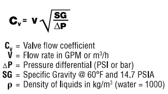
Understanding Flow Coefficient (Cv)
The flow coefficient (Cv) is a critical parameter in calculating the flow rate of a control valve. It represents the amount of fluid that can flow through the valve with a pressure drop of 1 pound per square inch (PSI). To determine the Cv value, you can use the following formula: Cv = Q / sqrt(ΔP), where Q is the flow rate and ΔP is the pressure drop. Here are the steps to calculate Cv:
- Measure the flow rate (Q) in GPM
- Measure the pressure drop (ΔP) in PSI
- Calculate the Cv value using the formula
Calculating Flow Rate Using Cv
Once you have determined the Cv value, you can calculate the flow rate of the control valve using the following formula: Q = Cv sqrt(ΔP). This formula assumes that the fluid is incompressible and that the valve is operating at a steady-state condition. Here are the steps to calculate the flow rate:
- Determine the Cv value from the manufacturer's data or by calculation
- Measure the pressure drop (ΔP) across the valve
- Calculate the flow rate (Q) using the formula
Effects of Valve Sizing on Flow Rate
The size of the control valve can significantly impact its flow rate. A larger valve can pass more fluid than a smaller valve, but it may also be more expensive and require more actuation force. To determine the correct valve size, you need to consider the required flow rate and the available pressure drop. Here are the factors to consider:
- Required flow rate (Q) in GPM
- Available pressure drop (ΔP) in PSI
- Valve sizing charts or tables provided by the manufacturer
Importance of Valve Type and Trim
The type of control valve and its trim can also affect the flow rate. Different valve types, such as globe, needle, or ball valves, have distinct flow characteristics. The trim, which refers to the valve's internal components, can also impact the flow rate. Here are the factors to consider:
- Valve type (e.g., globe, needle, ball)
- Trim type (e.g., linear, equal percentage)
- Valve manufacturer's data and recommendations
Considering Fluid Properties and Pipe Sizing
The properties of the fluid and the pipe sizing can also impact the flow rate of the control valve. Viscous fluids or high-temperature fluids may require special consideration. Additionally, the pipe size and friction loss can affect the flow rate. Here are the factors to consider:
- Fluid properties (e.g., viscosity, density)
- Pipe sizing and friction loss calculations
- Valve manufacturer's recommendations for fluid and pipe sizing
How to calculate control valve sizing?
To calculate control valve sizing, you need to consider several factors, including the type of valve, the fluid being controlled, and the desired flow rate. The goal of control valve sizing is to select a valve that can accurately control the flow rate of the fluid, while also providing the necessary pressure drop and flow characteristics. This involves calculating the valve coefficient (Cv) and the valve flow rate (Q), as well as considering factors such as fluid density, viscosity, and temperature.
Understanding Control Valve Sizing Basics
To calculate control valve sizing, you need to understand the basics of valve sizing and the types of valves available. This includes understanding the different valve types, such as linear valves and equal percentage valves, as well as the valve trim options, such as plug and seat or ball and cage. The following steps are involved in calculating control valve sizing:
- Determine the desired flow rate and pressure drop across the valve
- Calculate the valve coefficient (Cv) using the ISA formula or other industry-standard methods
- Select a valve that meets the calculated Cv and flow rate requirements
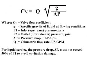
Calculating Valve Coefficient (Cv)
The valve coefficient (Cv) is a measure of the valve's ability to control flow, and is calculated using the ISA formula: Cv = Q / (G sqrt(ΔP / (G ρ))). To calculate Cv, you need to know the flow rate (Q), fluid density (ρ), and pressure drop (ΔP) across the valve. The following factors can affect the Cv calculation:
- Fluid properties, such as density and viscosity
- Valve type and trim options
- Pipe size and configuration
Determining Valve Flow Rate (Q)
The valve flow rate (Q) is the rate at which fluid flows through the valve, and is typically measured in gallons per minute (gpm) or cubic meters per hour (m3/h). To determine Q, you need to know the desired flow rate and the valve's flow characteristics, such as its flow curve and pressure drop. The following steps are involved in determining Q:
- Determine the maximum flow rate required by the process
- Calculate the valve's flow coefficient (Cv) using the ISA formula
- Select a valve that meets the calculated Q and Cv requirements
Selecting the Correct Valve Type
The type of valve used can significantly impact the control valve sizing calculation. Different valve types, such as linear valves and equal percentage valves, have different flow characteristics and pressure drop requirements. The following factors can affect the valve type selection:
- Process requirements, such as accuracy and response time
- Fluid properties, such as density and viscosity
- Pipe size and configuration
Considering Fluid Properties and Pipe Configuration
Fluid properties, such as density and viscosity, can significantly impact the control valve sizing calculation. Additionally, pipe size and configuration can affect the pressure drop and flow rate through the valve. The following factors can affect the fluid properties and pipe configuration:
- Fluid type, such as liquid or gas
- Fluid temperature and pressure
- Pipe material and size
What is the relationship between valve opening and flow rate?

The relationship between valve opening and flow rate is a fundamental concept in fluid dynamics. The valve opening refers to the degree to which a valve is open, allowing fluid to flow through it. The flow rate, on the other hand, is the volume of fluid that passes through a given area per unit time. As the valve opening increases, the flow rate also increases, but the relationship between the two is not always linear.
Valve Opening and Flow Rate Relationship
The relationship between valve opening and flow rate is influenced by several factors, including the valve type, size, and operating conditions. In general, as the valve opening increases, the flow rate also increases, but the rate of increase may vary depending on the valve characteristics. For example:
- The flow coefficient of a valve, which is a measure of its ability to allow fluid to flow through it, plays a significant role in determining the relationship between valve opening and flow rate.
- The valve opening percentage also affects the flow rate, with higher opening percentages resulting in higher flow rates.
- The fluid properties, such as density and viscosity, can also influence the relationship between valve opening and flow rate.
Factors Affecting Valve Opening and Flow Rate
Several factors can affect the relationship between valve opening and flow rate, including pipe size, fluid velocity, and valve configuration. For example:
- Pipe size can affect the flow rate, with larger pipes allowing for higher flow rates.
- Fluid velocity can also impact the flow rate, with higher velocities resulting in higher flow rates.
- Valve configuration, such as the type of valve and its orientation, can also influence the relationship between valve opening and flow rate.
Valve Types and Flow Rate
Different types of valves can have varying effects on the relationship between valve opening and flow rate. For example:
- Gate valves are designed to allow for high flow rates when fully open, but may have a more restricted flow rate when partially open.
- Globe valves are designed to provide a more linear relationship between valve opening and flow rate, making them suitable for applications where precise control is required.
- Ball valves are designed to provide a high flow rate when fully open, but may have a more restricted flow rate when partially open.
Conclusion of Valve Opening and Flow Rate
The relationship between valve opening and flow rate is complex and influenced by several factors. Understanding the valve characteristics, operating conditions, and fluid properties is crucial for optimizing the performance of a valve and ensuring the desired flow rate. For example:
- Valve sizing is critical to ensure that the valve is properly sized for the application.
- Valve maintenance is also essential to ensure that the valve operates efficiently and effectively.
- Valve selection should be based on the specific requirements of the application, taking into account factors such as flow rate, pressure, and temperature.
Applications of Valve Opening and Flow Rate
The relationship between valve opening and flow rate has numerous applications in various industries, including oil and gas, chemical processing, and power generation. For example:
- Flow control is critical in many industrial processes, where precise control of flow rate is required to ensure efficient and safe operation.
- Pressure regulation is also essential in many applications, where the pressure of the fluid must be controlled to prevent damage to equipment or ensure safe operation.
- Process optimization can be achieved by optimizing the relationship between valve opening and flow rate, resulting in improved efficiency, reduced costs, and increased productivity.
What is the difference between control valve and flow control valve?
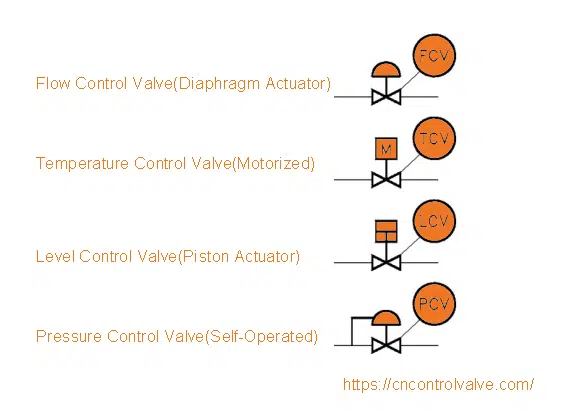
The primary difference between a control valve and a flow control valve lies in their functional purpose. A control valve is a device that regulates the flow of fluid, such as gas or liquid, by adjusting the size of the valve opening. On the other hand, a flow control valve is specifically designed to regulate the flow rate of a fluid to a predetermined setpoint.
Introduction to Control Valves
Control valves are used in a wide range of applications, including process control, hydraulic systems, and pneumatic systems. These valves operate by adjusting the valve opening to control! the flow rate, pressure, or temperature of the fluid. The main goal of a control valve is to maintain a specific process condition, such as pressure, temperature, or flow rate, within a predetermined range.
- The control valve receives a signal from a sensing device, which measures the process condition.
- The signal is then sent to a controller, which compares the measured value to the desired setpoint.
- The controller then sends a signal to the control valve, which adjusts the valve opening to maintain the desired process condition.
Introduction to Flow Control Valves
Flow control valves are used to regulate the flow rate of a fluid to a specific setpoint. These valves are designed to maintain a constant flow rate, regardless of changes in upstream pressure or downstream pressure. Flow control valves are commonly used in applications where a precise flow rate is required, such as in chemical processing, oil and gas production, and power generation.
- The flow control valve uses a sensing element to measure the flow rate of the fluid.
- The measured flow rate is then compared to the desired setpoint.
- The valve adjusts its opening to maintain the desired flow rate, ensuring that the process operates within the required parameters.
Key Differences between Control Valves and Flow Control Valves
The key differences between control valves and flow control valves lie in their functional purpose and operating characteristics. Control valves are designed to regulate a wide range of process conditions, while flow control valves are specifically designed to regulate the flow rate of a fluid.
- Control valves are often used in feedback control loops, where the valve adjusts its opening based on a feedback signal from a sensing device.
- Flow control valves, on the other hand, are used in feedforward control loops, where the valve adjusts its opening based on a predicted flow rate.
- The accuracy and repeatability of flow control valves are typically higher than those of control valves, due to their specific design purpose.
Applications of Control Valves and Flow Control Valves
Control valves and flow control valves are used in a wide range of applications, including process control, hydraulic systems, and pneumatic systems. The choice between a control valve and a flow control valve depends on the specific requirements of the application.
- Control valves are commonly used in chemical processing, oil and gas production, and power generation.
- Flow control valves are often used in water treatment, wastewater treatment, and food processing.
- The selection of a control valve or flow control valve depends on factors such as flow rate, pressure, and temperature requirements.
Selection Criteria for Control Valves and Flow Control Valves
The selection of a control valve or flow control valve depends on several factors, including flow rate, pressure, and temperature requirements. Other factors, such as accuracy, repeatability, and response time, must also be considered.
- The type of fluid being controlled, such as gas or liquid, must be considered when selecting a control valve or flow control valve.
- The operating conditions, such as temperature and pressure, must also be considered.
- The desired level of accuracy and repeatability must be specified, as well as the required response time.
Frequently Asked Questions (FAQs)
What is the purpose of the Control Valve P1 P2 vs Flow Spreadsheet Calculator?
The Control Valve P1 P2 vs Flow Spreadsheet Calculator is a powerful tool designed to help engineers and technicians calculate and analyze the performance of control valves in various fluid flow applications. The calculator allows users to input pressure and flow rate values, and then calculates the corresponding pressure drop and flow coefficient. This information is crucial in determining the optimization of control valve performance, as it enables users to identify potential bottlenecks and inefficiencies in the system. By using the calculator, users can streamline their workflow, reduce errors, and improve the overall efficiency of their control valve systems.
How does the Control Valve P1 P2 vs Flow Spreadsheet Calculator account for different types of fluid flow?
The Control Valve P1 P2 vs Flow Spreadsheet Calculator takes into account various types of fluid flow, including laminar flow, turbulent flow, and transitional flow. The calculator uses complex algorithms and mathematical models to simulate the behavior of different fluids and gases under various pressure and temperature conditions. By inputting the relevant fluid properties, such as density, viscosity, and specific heat capacity, users can obtain accurate calculations and predictions of the control valve's performance. The calculator also allows users to select from a range of correlation models, including the Darcy-Weisbach equation and the Colebrook-White equation, to account for the specific flow characteristics of their application.
Can the Control Valve P1 P2 vs Flow Spreadsheet Calculator be used for both liquid and gas applications?
Yes, the Control Valve P1 P2 vs Flow Spreadsheet Calculator can be used for both liquid and gas applications. The calculator is designed to be flexible and versatile, allowing users to input the relevant fluid properties and operating conditions for their specific application. Whether you are working with water, steam, air, or other gases, the calculator can handle the unique challenges and requirements of each fluid type. The calculator also accounts for the compressibility of gases, vapor pressure of liquids, and other key factors that can affect control valve performance. By using the calculator, users can ensure that their control valve system is optimized for their specific application, whether it involves liquid or gas flow.
How can I use the Control Valve P1 P2 vs Flow Spreadsheet Calculator to troubleshoot control valve problems?
The Control Valve P1 P2 vs Flow Spreadsheet Calculator can be a valuable tool for troubleshooting control valve problems. By inputting the relevant operating conditions and fluid properties, users can identify potential issues and bottlenecks in their control valve system. The calculator can help users diagnose problems such as insufficient flow rate, excessive pressure drop, or oscillations in the system. By analyzing the calculated pressure and flow rate values, users can determine the root cause of the problem and develop a solution to optimize the control valve's performance. The calculator can also be used to test and validate potential solutions, allowing users to refine their approach and ensure that the control valve system is operating efficiently and effectively.
Deja una respuesta
Entradas Relacionadas