
Cavitation Centrifugal Pump Minimum Safe Suction Head Formulas and Calculator

The Cavitation Centrifugal Pump Minimum Safe Suction Head is a critical parameter in ensuring the efficient and reliable operation of centrifugal pumps. Cavitation occurs when the pressure of a fluid falls below its vapor pressure, resulting in the formation of vapor bubbles. This can lead to damage to the pump and reduced performance. To avoid cavitation, it is essential to maintain a minimum safe suction head, which can be calculated using specific formulas and tools. This article provides an overview of the formulas and a calculator to determine the minimum safe suction head for centrifugal pumps.
- Cavitation Centrifugal Pump Minimum Safe Suction Head Formulas and Calculator
- How to calculate pump suction head?
- What is the formula for head of centrifugal pump?
- What is the suction limit of a centrifugal pump?
- What is the minimum pressure to avoid cavitation?
-
Frequently Asked Questions (FAQs)
- What is the concept of Minimum Safe Suction Head in Cavitation Centrifugal Pumps?
- How do you calculate the Minimum Safe Suction Head for a Cavitation Centrifugal Pump?
- What are the key factors that affect the Minimum Safe Suction Head in Cavitation Centrifugal Pumps?
- How can you use a calculator to determine the Minimum Safe Suction Head for a Cavitation Centrifugal Pump?
Cavitation Centrifugal Pump Minimum Safe Suction Head Formulas and Calculator
The Cavitation Centrifugal Pump Minimum Safe Suction Head is a critical parameter in the design and operation of centrifugal pumps. It refers to the minimum suction head required to prevent cavitation in the pump. Cavitation occurs when the pressure of the fluid being pumped drops below the vapor pressure, causing the formation of bubbles or voids in the fluid. This can lead to damage to the pump and reduced efficiency. The Minimum Safe Suction Head is calculated using formulas that take into account the pump's design, operating conditions, and fluid properties.
Understanding Cavitation in Centrifugal Pumps
Cavitation is a complex phenomenon that occurs when the pressure of the fluid being pumped drops below the vapor pressure. This can happen when the suction head is too low, or when the pump is operating at a high speed or low pressure. Cavitation can cause damage to the pump's impeller, casing, and bearings, as well as reduce the pump's efficiency and service life. To prevent cavitation, it is essential to ensure that the suction head is sufficient to maintain a stable and continuous flow of fluid through the pump.
Calculating Minimum Safe Suction Head
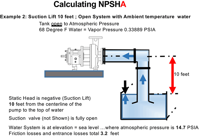
The Minimum Safe Suction Head is calculated using formulas that take into account the pump's design, operating conditions, and fluid properties. The most commonly used formula is the Net Positive Suction Head (NPSH) formula, which is given by: NPSH = (P1 - Pv) / ρ + (V1^2 / 2g), where P1 is the suction pressure, Pv is the vapor pressure, ρ is the fluid density, V1 is the suction velocity, and g is the acceleration due to gravity.
Factors Affecting Minimum Safe Suction Head
Several factors can affect the Minimum Safe Suction Head, including the pump's design, operating conditions, and fluid properties. The pump's design includes the impeller and casing geometry, as well as the pump's speed and power. The operating conditions include the suction pressure, discharge pressure, and flow rate. The fluid properties include the density, viscosity, and vapor pressure.
Using a Calculator to Determine Minimum Safe Suction Head
A calculator can be used to determine the Minimum Safe Suction Head by plugging in the relevant values and parameters. The calculator can take into account the pump's design, operating conditions, and fluid properties to provide an accurate calculation of the Minimum Safe Suction Head. The calculator can also provide a graphical representation of the NPSH curve, which can be used to visualize the pump's performance and identify potential problems.
Importance of Minimum Safe Suction Head in Pump Selection
The Minimum Safe Suction Head is a critical parameter in the selection of a centrifugal pump. It is essential to ensure that the pump is capable of operating at a suction head that is sufficient to prevent cavitation. A pump that is not capable of operating at a sufficient suction head can experience reduced efficiency, increased maintenance, and premature failure. The following table provides a summary of the key parameters that affect the Minimum Safe Suction Head:
| Parameter | Description |
|---|---|
| Pump Design | Affects the NPSH required to prevent cavitation |
| Operating Conditions | Affects the NPSH required to prevent cavitation |
| Fluid Properties | Affects the NPSH required to prevent cavitation |
| Suction Pressure | Affects the NPSH required to prevent cavitation |
| Suction Velocity | Affects the NPSH required to prevent cavitation |
How to calculate pump suction head?
To calculate pump suction head, it's essential to understand the concept of head in the context of fluid dynamics. The pump suction head, also known as negative suction head, is the pressure at the suction side of a pump, measured in terms of the height of a column of fluid. This value is crucial in determining the pump's performance and efficiency. The calculation involves several factors, including the fluid's density, viscosity, and the pump's design.
Understanding Pump Suction Head Terminology
Understanding the terminology related to pump suction head is vital for accurate calculations. Key terms include net positive suction head (NPSH), which is the difference between the absolute pressure at the pump suction and the vapor pressure of the fluid, and suction head, which refers to the vertical distance between the pump suction and the fluid level. These terms are critical in determining the pump's operating conditions.
- NPSH is a measure of the pressure available at the pump suction to overcome the vapor pressure of the fluid.
- Suction head is influenced by the fluid's density and the pump's suction design.
- Absolute pressure is the pressure measured relative to a perfect vacuum, and it's essential in calculating the NPSH.
Factors Affecting Pump Suction Head Calculation
Several factors can affect the calculation of pump suction head, including the fluid's properties, such as density and viscosity, the pump's design and operating conditions, and the system's configuration, including pipe sizes and fittings. These factors can influence the pressure drop and flow rate, impacting the pump's performance. Identifying and accounting for these factors is crucial for accurate calculations.
- Fluid properties like density and viscosity directly influence the pump's suction head.
- Pump design features, such as impeller shape and suction pipe size, affect the pump's efficiency and suction head.
- System configuration elements, including valves and fittings, contribute to pressure drop and impact the pump's performance.
Calculation Methodologies for Pump Suction Head
There are several methodologies for calculating pump suction head, including the use of charts and formulas provided by pump manufacturers, and more complex computer simulations that account for various system variables. These methods help in determining the optimal operating conditions for the pump and ensuring efficient operation.
- Pump performance curves are used to determine the pump's efficiency and suction head at different flow rates.
- NPSH calculations involve determining the absolute pressure at the pump suction and subtracting the vapor pressure of the fluid.
- Computer-aided design (CAD) software and fluid dynamics simulations can provide detailed insights into the pump's performance and system interactions.
Importance of Accurate Pump Suction Head Calculation
Accurate calculation of pump suction head is crucial for ensuring the pump's reliability and efficiency. Incorrect calculations can lead to cavitation, reduced flow rates, and increased energy consumption, ultimately affecting the overall system performance. Therefore, it's essential to carefully consider all factors and use appropriate methodologies for calculating pump suction head.
- Cavitation can occur if the NPSH is not sufficient, leading to damage to the pump and reduced lifespan.
- Efficient operation requires optimal pump suction head to minimize energy consumption and maximize flow rates.
- System performance is directly impacted by the pump's suction head, making accurate calculations vital for overall system efficiency.
Tools and Resources for Pump Suction Head Calculation
Various tools and resources are available for calculating pump suction head, including pump manufacturer's documentation, online calculators, and professional engineering software. These resources provide guidelines, formulas, and simulation tools to help engineers and technicians accurately calculate pump suction head and ensure optimal system performance.
- Pump manufacturer's documentation often includes performance curves and NPSH data for specific pumps.
- Online calculators and engineering software can simplify the calculation process and provide detailed analysis of the system.
- Professional engineering consultancies can offer expert advice and customized solutions for complex pump suction head calculations.
What is the formula for head of centrifugal pump?
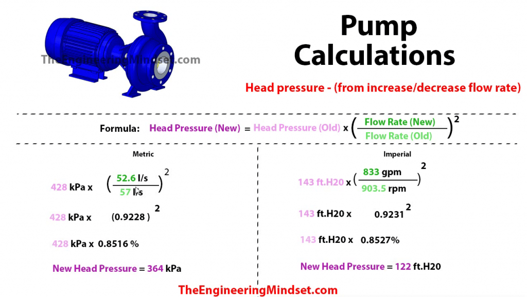
The formula for the head of a centrifugal pump is given by the equation H = (P2 - P1) / (ρ g) + (V2^2 - V1^2) / (2 g) + (z2 - z1), where H is the head, P1 and P2 are the pressures at the inlet and outlet, ρ is the density of the fluid, g is the acceleration due to gravity, V1 and V2 are the velocities at the inlet and outlet, and z1 and z2 are the elevations of the inlet and outlet.
Components of the Head Formula
The head formula for a centrifugal pump consists of several components, including the pressure head, velocity head, and elevation head. These components are combined to determine the total head of the pump.
- The pressure head is the difference in pressure between the inlet and outlet of the pump, divided by the product of the fluid density and the acceleration due to gravity.
- The velocity head is the difference in the squares of the velocities at the inlet and outlet, divided by twice the acceleration due to gravity.
- The elevation head is the difference in elevation between the inlet and outlet of the pump.
Importance of Head in Centrifugal Pumps
The head of a centrifugal pump is a critical parameter in determining its performance and efficiency. It is essential to consider the head when selecting a pump for a specific application, as it affects the pump's ability to overcome friction losses and elevation changes in the piping system.
- The head of a pump is directly related to its flow rate and pressure characteristics.
- A higher head requires a more powerful pump, which can increase energy consumption and operating costs.
- The head of a pump can also affect its cavitation and vibration characteristics, which can impact its reliability and maintenance requirements.
Factors Affecting Head in Centrifugal Pumps
Several factors can affect the head of a centrifugal pump, including the impeller design, pump speed, and fluid properties.
- The impeller design can significantly impact the head of a pump, as it affects the velocity and pressure characteristics of the fluid.
- The pump speed can also affect the head, as it influences the velocity and pressure of the fluid.
- The fluid properties, such as density and viscosity, can also impact the head of a pump, as they affect the friction losses and energy consumption.
Calculating Head in Centrifugal Pumps
Calculating the head of a centrifugal pump requires a thorough understanding of the pump characteristics and the system parameters.
- The pump characteristic curve provides the relationship between the head and flow rate of the pump.
- The system parameters, such as the friction losses and elevation changes, must be considered when calculating the head.
- The head calculation can be performed using various methods, including the use of formulas and charts.
Applications of Head in Centrifugal Pumps
The head of a centrifugal pump has various applications in different industries, including water supply, wastewater treatment, and chemical processing.
- In water supply systems, the head of a pump is critical in determining its ability to supply water to elevated areas.
- In wastewater treatment plants, the head of a pump is essential in determining its ability to handle high-pressure applications.
- In chemical processing plants, the head of a pump is important in determining its ability to handle corrosive and high-temperature fluids.
What is the suction limit of a centrifugal pump?

The suction limit of a centrifugal pump is the maximum suction pressure or vacuum that the pump can withstand while still functioning properly. This limit is determined by the pump's design and construction, as well as the properties of the fluid being pumped. Exceeding the suction limit can lead to cavitation, which can cause damage to the pump and reduce its efficiency.
Understanding Suction Limit
The suction limit is an important consideration in the design and operation of centrifugal pumps. It is typically measured in terms of feet of head or pounds per square inch (psi). The suction limit is influenced by factors such as the pump's impeller design, shaft speed, and fluid properties. To understand the suction limit, it is essential to consider the following factors:
- The net positive suction head (NPSH) required by the pump, which is the difference between the total suction head and the vapor pressure of the fluid.
- The suction pressure or vacuum that the pump is subjected to, which can affect the formation of vapor bubbles and cavitation.
- The pump's materials and construction, which can impact its ability to withstand corrosion and wear caused by cavitation.
Factors Affecting Suction Limit
Several factors can affect the suction limit of a centrifugal pump, including the fluid's viscosity, temperature, and composition. The pump's speed and impeller design can also impact the suction limit. Additionally, the suction piping and valves can influence the pressure drop and flow rate, which can affect the suction limit. Some key factors to consider are:
- The fluid's density and viscosity, which can affect the pressure drop and flow rate through the pump.
- The pump's shaft speed and impeller design, which can impact the head and flow rate developed by the pump.
- The suction piping and valves, which can influence the pressure drop and flow rate through the pump.
Cavitation and Its Effects
Cavitation is a phenomenon that occurs when the suction pressure or vacuum exceeds the vapor pressure of the fluid, causing the formation of vapor bubbles. These bubbles can collapse with great force, causing damage to the pump's impeller and other components. Cavitation can lead to a range of problems, including:
- Reduced pump efficiency and flow rate, due to the formation of vapor bubbles and cavitation.
- Increased wear and tear on the pump's components, caused by the collapse of vapor bubbles.
- Noise and vibration, resulting from the cavitation and turbulence caused by the collapse of vapor bubbles.
Measuring Suction Limit
The suction limit of a centrifugal pump can be measured using a variety of techniques, including:
- Pressure gauges and transmitters, which can measure the suction pressure or vacuum.
- Flow meters, which can measure the flow rate through the pump.
- Vibration sensors, which can detect the vibration caused by cavitation and turbulence.
These measurements can be used to determine the net positive suction head (NPSH) required by the pump and to identify potential problems with cavitation and wear.
Designing for Suction Limit
To design a centrifugal pump that operates within its suction limit, it is essential to consider the fluid properties, pump design, and operating conditions. The pump's impeller and shaft should be designed to withstand the stress and wear caused by cavitation and turbulence. Some key considerations include:
- Selecting materials that can withstand corrosion and wear caused by cavitation.
- Designing the impeller to minimize cavitation and turbulence.
- Specifying operating conditions that are within the pump's suction limit.
What is the minimum pressure to avoid cavitation?

The minimum pressure to avoid cavitation is a critical parameter in various engineering applications, including pumps, turbines, and pipelines. To determine this minimum pressure, it is essential to understand the concept of cavitation and its effects on fluid flow. Cavitation occurs when the pressure of a fluid falls below its vapor pressure, causing the formation of vapor bubbles or cavities. These cavities can collapse with significant force, leading to erosion, noise, and vibration.
Understanding Cavitation
To avoid cavitation, it is crucial to maintain the pressure of the fluid above its vapor pressure. This can be achieved by increasing the pressure at the inlet of the system or by reducing the velocity of the fluid. The minimum pressure to avoid cavitation depends on various factors, including the fluid properties, flow rate, and system geometry. Some key factors to consider when determining the minimum pressure to avoid cavitation include:
- Fluid properties: The viscosity, surface tension, and vapor pressure of the fluid can affect the likelihood of cavitation.
- Flow rate: Higher flow rates can increase the velocity of the fluid, making it more susceptible to cavitation.
- System geometry: The design of the system, including the inlet and outlet configurations, can influence the pressure distribution and flow patterns.
Cavitation in Pumps
In pumps, cavitation can occur when the suction pressure is too low, causing the formation of vapor bubbles at the inlet. To avoid cavitation in pumps, it is essential to ensure that the suction pressure is above the vapor pressure of the fluid. This can be achieved by increasing the pressure at the inlet or by using a pump with a higher net positive suction head (NPSH). Some key considerations when selecting a pump to avoid cavitation include:
- NPSH: The NPSH of the pump should be higher than the NPSH required by the system.
- Pump speed: The speed of the pump can affect the pressure distribution and flow patterns.
- Pump design: The design of the pump, including the impeller and volute, can influence the pressure distribution and flow patterns.
Cavitation in Turbines
In turbines, cavitation can occur when the pressure at the inlet is too low, causing the formation of vapor bubbles. To avoid cavitation in turbines, it is essential to ensure that the pressure at the inlet is above the vapor pressure of the fluid. This can be achieved by increasing the pressure at the inlet or by using a turbine with a higher inlet pressure. Some key considerations when selecting a turbine to avoid cavitation include:
- Inlet pressure: The inlet pressure of the turbine should be higher than the vapor pressure of the fluid.
- Turbine speed: The speed of the turbine can affect the pressure distribution and flow patterns.
- Turbine design: The design of the turbine, including the blades and hub, can influence the pressure distribution and flow patterns.
Cavitation in Pipelines
In pipelines, cavitation can occur when the pressure falls below the vapor pressure of the fluid, causing the formation of vapor bubbles. To avoid cavitation in pipelines, it is essential to ensure that the pressure is above the vapor pressure of the fluid throughout the pipeline. This can be achieved by increasing the pressure at the inlet or by using pressure-boosting devices, such as pumps or compressors. Some key considerations when designing a pipeline to avoid cavitation include:
- Pipeline material: The material of the pipeline can affect the pressure distribution and flow patterns.
- Pipeline diameter: The diameter of the pipeline can affect the pressure distribution and flow patterns.
- Pipeline layout: The layout of the pipeline, including the inlet and outlet configurations, can influence the pressure distribution and flow patterns.
Methods to Avoid Cavitation
To avoid cavitation, several methods can be employed, including:
- Increasing the pressure: Increasing the pressure at the inlet can help to avoid cavitation.
- Reducing the velocity: Reducing the velocity of the fluid can help to avoid cavitation.
- Using cavitation-resistant materials: Using materials that are resistant to cavitation can help to minimize the effects of cavitation.
Frequently Asked Questions (FAQs)
What is the concept of Minimum Safe Suction Head in Cavitation Centrifugal Pumps?
The concept of Minimum Safe Suction Head (NPSH) is crucial in the design and operation of cavitation centrifugal pumps. It refers to the minimum net positive suction head required to prevent cavitation from occurring in the pump. Cavitation is a phenomenon where vapour bubbles form and collapse, causing damage to the pump and reducing its efficiency. The Minimum Safe Suction Head is determined by the pump's design and the properties of the fluid being pumped, such as its density, viscosity, and vapour pressure. By ensuring that the suction head is above the Minimum Safe Suction Head, pump operators can prevent cavitation and ensure reliable and efficient operation of the pump.
How do you calculate the Minimum Safe Suction Head for a Cavitation Centrifugal Pump?
Calculating the Minimum Safe Suction Head for a cavitation centrifugal pump involves using a combination of formulas and empirical correlations. The most commonly used formula is the Net Positive Suction Head (NPSH) equation, which takes into account the static suction head, friction losses, and velocity head. The equation is: NPSH = Hs - Hf - Hv, where Hs is the static suction head, Hf is the friction loss, and Hv is the velocity head. Additionally, the pump's performance curve and cavitation characteristics must be considered to determine the Minimum Safe Suction Head. Computer simulations and experimental testing can also be used to validate the calculations and ensure accurate determination of the Minimum Safe Suction Head.
What are the key factors that affect the Minimum Safe Suction Head in Cavitation Centrifugal Pumps?
Several key factors affect the Minimum Safe Suction Head in cavitation centrifugal pumps, including the pump's design, operating conditions, and fluid properties. The pump's design parameters, such as the impeller diameter, suction nozzle size, and volute geometry, can significantly impact the Minimum Safe Suction Head. The operating conditions, including the flow rate, pressure, and temperature, also play a crucial role in determining the Minimum Safe Suction Head. Furthermore, the fluid properties, such as its density, viscosity, and vapour pressure, can affect the Minimum Safe Suction Head. Other factors, including piping layout, valve sizing, and control systems, can also influence the Minimum Safe Suction Head and must be carefully considered in the design and operation of the pump.
How can you use a calculator to determine the Minimum Safe Suction Head for a Cavitation Centrifugal Pump?
Using a calculator to determine the Minimum Safe Suction Head for a cavitation centrifugal pump can be a convenient and accurate way to evaluate the pump's performance. The calculator can take into account various input parameters, such as the pump's design, operating conditions, and fluid properties, to calculate the Minimum Safe Suction Head. The calculator can also account for complex correlations and empirical formulas that are difficult to evaluate manually. By inputting the relevant data into the calculator, users can quickly and easily determine the Minimum Safe Suction Head and ensure that the pump is operating within a safe and efficient range. Additionally, the calculator can be used to simulate different operating scenarios and design configurations, allowing users to optimize the pump's performance and minimize the risk of cavitation.
Deja una respuesta
Entradas Relacionadas