
2D Finite Element Analysis Spreadsheet Calculator

The 2D Finite Element Analysis Spreadsheet Calculator is a powerful tool for engineers and researchers to analyze and simulate various physical phenomena in two-dimensional space. This calculator utilizes the finite element method to discretize complex problems into smaller, manageable parts, allowing for accurate calculations and predictions. With its user-friendly interface and robust functionality, the calculator enables users to model and analyze problems in fields such as mechanics, heat transfer, and fluid dynamics, making it an essential resource for professionals and students alike. It provides a comprehensive and efficient means of performing complex calculations.
-
2D Finite Element Analysis Spreadsheet Calculator: A Comprehensive Tool for Engineers
- Introduction to 2D Finite Element Analysis
- Key Features of the 2D Finite Element Analysis Spreadsheet Calculator
- Applications of the 2D Finite Element Analysis Spreadsheet Calculator
- Benefits of Using the 2D Finite Element Analysis Spreadsheet Calculator
- Limitations and Future Developments of the 2D Finite Element Analysis Spreadsheet Calculator
- Can AutoCAD do finite element analysis?
- How do you validate finite element analysis?
- What is 3D finite element analysis?
-
Frequently Asked Questions (FAQs)
- What is 2D Finite Element Analysis Spreadsheet Calculator and its purpose?
- How does the 2D Finite Element Analysis Spreadsheet Calculator work?
- What are the benefits of using the 2D Finite Element Analysis Spreadsheet Calculator?
- What kind of problems can be solved using the 2D Finite Element Analysis Spreadsheet Calculator?
2D Finite Element Analysis Spreadsheet Calculator: A Comprehensive Tool for Engineers
The 2D Finite Element Analysis Spreadsheet Calculator is a powerful tool used by engineers to analyze and simulate the behavior of complex systems and structures under various loads and conditions. This calculator utilizes the finite element method to divide a system into smaller, manageable parts, called elements, and then applies mathematical equations to predict the behavior of each element and the overall system.
Introduction to 2D Finite Element Analysis
2D Finite Element Analysis is a numerical method used to simulate the behavior of systems and structures in two dimensions. This method is widely used in various fields, including mechanical engineering, civil engineering, and aerospace engineering, to analyze the stress, strain, and deformation of structures under different loads and conditions. The 2D Finite Element Analysis Spreadsheet Calculator is a useful tool for engineers to perform these analyses and obtain accurate results.
Key Features of the 2D Finite Element Analysis Spreadsheet Calculator
The 2D Finite Element Analysis Spreadsheet Calculator has several key features that make it a powerful tool for engineers. These features include:
| Feature | Description |
|---|---|
| Mesh Generation | The calculator can automatically generate a mesh of elements for the system being analyzed. |
| Material Properties | The calculator allows users to input the material properties of the system, such as elastic modulus and Poisson's ratio. |
| Load Application | The calculator enables users to apply various types of loads, including point loads, distributed loads, and thermal loads. |
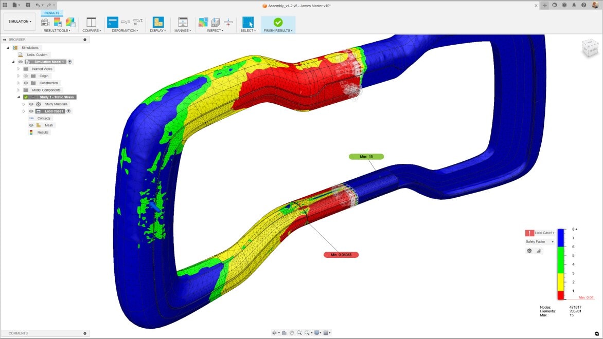
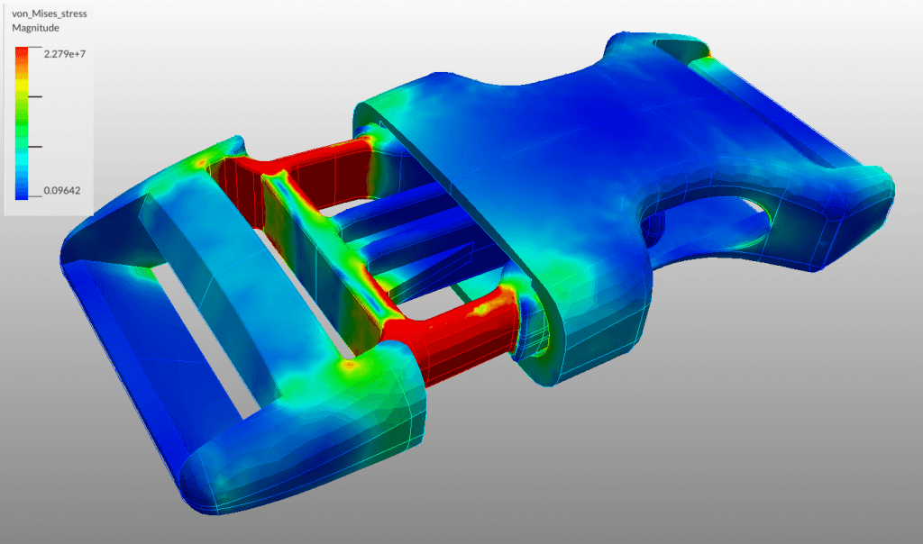
| Results Visualization | The calculator provides a range of visualization tools to help users interpret the results of the analysis, including contour plots and vector plots. |
| Validation and Verification | The calculator includes tools for validating and verifying the results of the analysis, such as error estimation and sensitivity analysis. |
Applications of the 2D Finite Element Analysis Spreadsheet Calculator
The 2D Finite Element Analysis Spreadsheet Calculator has a wide range of applications in various fields, including:
Structural analysis: The calculator can be used to analyze the stress and deformation of buildings, bridges, and other structures under different loads and conditions.
Mechanical engineering: The calculator can be used to analyze the performance of mechanical systems, such as gears, bearings, and pumps.
Aerospace engineering: The calculator can be used to analyze the aerodynamic and aeroelastic behavior of aircraft and spacecraft.
Benefits of Using the 2D Finite Element Analysis Spreadsheet Calculator
The 2D Finite Element Analysis Spreadsheet Calculator offers several benefits to engineers, including:
Increased accuracy: The calculator can provide more accurate results than traditional analytical methods.
Reduced computational time: The calculator can perform complex analyses quickly and efficiently.
Improved design optimization: The calculator can be used to optimize the design of systems and structures by analyzing the effects of different design variables.
Limitations and Future Developments of the 2D Finite Element Analysis Spreadsheet Calculator
While the 2D Finite Element Analysis Spreadsheet Calculator is a powerful tool, it has some limitations, including:
Assumptions and simplifications: The calculator relies on various assumptions and simplifications, such as the plane stress and plane strain assumptions.
Limited geometric complexity: The calculator is limited to analyzing systems with relatively simple geometries.
Future developments of the calculator may include the incorporation of artificial intelligence and machine learning techniques to improve the accuracy and efficiency of the analysis.
Can AutoCAD do finite element analysis?
AutoCAD can be used for finite element analysis (FEA) to some extent, but it is not a dedicated FEA software. While AutoCAD has some built-in tools for simulating and analyzing the behavior of objects under various loads and stresses, it is primarily a computer-aided design (CAD) software. For more complex and advanced FEA, users typically rely on specialized software such as Autodesk Simulation or third-party tools that integrate with AutoCAD.
Introduction to Finite Element Analysis in AutoCAD
Finite element analysis in AutoCAD involves breaking down a complex object into smaller, simpler components called finite elements. These elements are then analyzed individually to determine how they behave under different loads and stresses. The results are then combined to provide an overall understanding of the object's behavior. This process can be used to simulate various scenarios, such as stress analysis, thermal analysis, and dynamic analysis.
- The finite element method is a numerical technique used to solve partial differential equations (PDEs) in various fields of physics and engineering.
- AutoCAD's FEA capabilities are limited compared to dedicated FEA software, but it can still be used for simple to moderate complexity analyses.
- The AutoCAD Simulation toolset provides a more comprehensive set of FEA tools, including static stress, dynamic, and thermal analysis.
Limitations of AutoCAD for Finite Element Analysis
While AutoCAD can be used for FEA, there are several limitations to its capabilities. For example, AutoCAD's FEA tools are not as powerful as those found in dedicated FEA software, and the software may not be able to handle complex or large-scale analyses. Additionally, the results of FEA simulations in AutoCAD may not be as accurate or reliable as those obtained using specialized software.
- AutoCAD's FEA tools are primarily designed for simple to moderate complexity analyses, and may not be suitable for very complex or large-scale analyses.
- The accuracy and reliability of FEA results in AutoCAD depend on various factors, including the quality of the input data and the complexity of the analysis.
- Dedicated FEA software, such as ANSYS or ABAQUS, offer more advanced and specialized tools for FEA, including higher-order elements and more sophisticated material models.
Applications of Finite Element Analysis in AutoCAD
FEA in AutoCAD can be applied to a wide range of fields, including mechanical engineering, civil engineering, and architectural engineering. It can be used to analyze the behavior of various types of structures, such as bridges, buildings, and machinery. Additionally, FEA can be used to optimize the design of objects and systems, reducing weight, cost, and material usage while maintaining or improving performance and safety.
- FEA can be used to analyze the stress and strain on a object under different loads and conditions, helping to identify potential weak points and failure modes.
- The thermal analysis capabilities of AutoCAD can be used to simulate the heat transfer and temperature distribution in a system or object.
- AutoCAD's FEA tools can also be used for dynamic analysis, simulating the motion and vibration of objects and systems over time.
Integration with Other Software for Finite Element Analysis
AutoCAD can be integrated with other software, such as Autodesk Simulation or Nastran, to provide more advanced FEA capabilities. This can include the use of more sophisticated material models, higher-order finite elements, and more advanced solver algorithms. Additionally, the integration with other software can provide access to more specialized tools and features, such as optimization and sensitivity analysis.
- The Autodesk Simulation toolset provides a more comprehensive set of FEA tools, including static stress, dynamic, and thermal analysis.
- The Nastran software is a general-purpose FEA solver that can be used for a wide range of analyses, including static, dynamic, and thermal.
- Other software, such as ANSYS or ABAQUS, offer more advanced and specialized tools for FEA, including higher-order elements and more sophisticated material models.
Best Practices for Finite Element Analysis in AutoCAD
To get the most out of FEA in AutoCAD, it is essential to follow best practices, such as using high-quality meshes, selecting the appropriate material models, and validating the results of the analysis. Additionally, users should be aware of the limitations and assumptions of the FEA method, and take steps to verify and validate the results.
- Using high-quality meshes is critical for obtaining accurate and reliable FEA results, as a poor-quality mesh can lead to inaccurate or unreliable results.
- Selecting the appropriate material models is also essential, as the choice of material model can significantly affect the accuracy and reliability of the FEA results.
- Validating the results of the FEA analysis is crucial, as it helps to ensure that the results are accurate and reliable, and that the analysis is robust and reliable.
How do you validate finite element analysis?
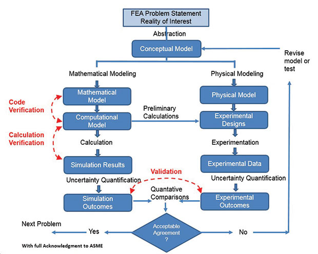
Validating finite element analysis (FEA) is a crucial step in ensuring the accuracy and reliability of the results obtained from simulations. This process involves verifying that the numerical model accurately represents the physical behavior of the system being analyzed. The validation process typically involves comparing the FEA results with experimental data or analytical solutions. The goal is to ensure that the finite element model is able to predict the behavior of the system with a high degree of accuracy, including factors such as stress, strain, and displacement.
Introduction to Validation Methods
There are several methods that can be used to validate FEA results, including comparing the results with experimental data, benchmark problems, and analytical solutions. The choice of validation method depends on the specific application and the type of analysis being performed. For example, in structural analysis, the validation method may involve comparing the FEA results with experimental data from laboratory tests. The following are some common validation methods:
- Experimental validation: Comparing FEA results with experimental data from laboratory tests or field measurements.
- Benchmark problems: Comparing FEA results with known solutions for well-defined problems.
- Analytical validation: Comparing FEA results with analytical solutions for simple problems.
Importance of Boundary Conditions
The boundary conditions used in the FEA model can have a significant impact on the accuracy of the results. The boundary conditions must accurately represent the physical behavior of the system, including factors such as loads, constraints, and contacts. The following are some key considerations for boundary conditions:
- Load application: The loads must be applied in a way that accurately represents the physical behavior of the system.
- Constraint definition: The constraints must be defined in a way that accurately represents the physical behavior of the system.
- Contact modeling: The contacts between different components must be modeled accurately to capture the physical behavior of the system.
Role of Material Properties
The material properties used in the FEA model can also have a significant impact on the accuracy of the results. The material properties must accurately represent the physical behavior of the materials, including factors such as elasticity, plasticity, and viscosity. The following are some key considerations for material properties:
- Elastic properties: The elastic properties of the materials, such as Young's modulus and Poisson's ratio, must be accurately represented.
- Plastic properties: The plastic properties of the materials, such as yield strength and ultimate strength, must be accurately represented.
- Viscous properties: The viscous properties of the materials, such as viscosity and creep, must be accurately represented.
Techniques for Model Verification
There are several techniques that can be used to verify the FEA model, including sensitivity analysis, uncertainty analysis, and convergence analysis. The goal of these techniques is to ensure that the FEA model is robust and reliable, and that the results are accurate and consistent. The following are some common techniques for model verification:
- Sensitivity analysis: Analyzing the effect of input parameters on the FEA results.
- Uncertainty analysis: Analyzing the effect of uncertainty in the input parameters on the FEA results.
- Convergence analysis: Analyzing the effect of mesh refinement on the FEA results.
Best Practices for Validation
There are several best practices that can be followed to ensure that the FEA validation process is effective and efficient. The following are some key considerations:
- Clear objectives: The objectives of the validation process must be clearly defined.
- Well-defined validation metrics: The validation metrics must be well-defined and quantifiable.
- Systematic approach: The validation process must be systematic and methodical.
What is 3D finite element analysis?
3D finite element analysis is a numerical method used to simulate and analyze the behavior of complex systems, such as structures, mechanisms, and materials, in three-dimensional space. This method involves dividing the system into smaller, discrete elements, and then applying mathematical equations to analyze the behavior of each element and its interactions with neighboring elements. The resulting analysis provides a detailed understanding of the system's behavior under various loads and boundary conditions.
Introduction to 3D Finite Element Analysis
3D finite element analysis is a powerful tool used in various fields, including engineering, physics, and materials science. The analysis involves creating a 3D model of the system, which is then discretized into smaller elements, such as tetrahedra or hexahedra. The resulting mesh is used to solve partial differential equations that describe the behavior of the system. The solution provides a detailed understanding of the system's behavior, including stress, strain, and displacement.
- Mesh generation: The process of creating a 3D mesh from the system's geometry.
- Element formulation: The process of defining the mathematical equations that describe the behavior of each element.
- Solution methods: The techniques used to solve the system of equations, such as direct methods or iterative methods.
Applications of 3D Finite Element Analysis
3D finite element analysis has a wide range of applications, including structural analysis, thermal analysis, and fluid dynamics. The analysis can be used to simulate the behavior of complex systems, such as aircraft, automobiles, and medical devices. The results of the analysis can be used to optimize the design of the system, reduce cost and weight, and improve performance and safety.
- Structural integrity: The analysis of a system's ability to withstand loads and stresses.
- Thermal management: The analysis of a system's ability to manage heat transfer and temperature.
- Fluid flow: The analysis of a system's ability to manage fluid flow and pressure.
Benefits of 3D Finite Element Analysis
3D finite element analysis provides several benefits, including increased accuracy, reduced cost, and improved efficiency. The analysis can be used to simulate the behavior of complex systems, reducing the need for physical prototypes and experimental testing. The results of the analysis can be used to optimize the design of the system, reducing material waste and energy consumption.
- Improved design: The ability to optimize the design of a system using simulation-based design.
- Reduced testing: The ability to reduce the need for physical testing using simulation-based testing.
- Increased safety: The ability to analyze the safety of a system using simulation-based analysis.
Challenges of 3D Finite Element Analysis
3D finite element analysis also presents several challenges, including complexity, computational cost, and interpretation of results. The analysis requires advanced mathematical models and high-performance computing resources. The results of the analysis require expert interpretation to ensure that the correct conclusions are drawn.
- Model complexity: The difficulty of creating an accurate mathematical model of a complex system.
- Computational cost: The computational resources required to solve the system of equations.
- Result interpretation: The difficulty of interpreting the results of the analysis to ensure that the correct conclusions are drawn.
Future Developments in 3D Finite Element Analysis
3D finite element analysis is a rapidly evolving field, with new developments and advances being made regularly. The use of artificial intelligence and machine learning is becoming increasingly popular, enabling the automation of the analysis process and the improvement of the accuracy and efficiency of the results. The development of new materials and new technologies is also driving the need for more advanced and more sophisticated analysis tools.
- Artificial intelligence: The use of AI and ML to automate the analysis process and improve the accuracy and efficiency of the results.
- New materials: The development of new materials and new technologies that require more advanced analysis tools.
- High-performance computing: The development of high-performance computing resources that enable the fast and efficient solution of large-scale problems.
Frequently Asked Questions (FAQs)
What is 2D Finite Element Analysis Spreadsheet Calculator and its purpose?
The 2D Finite Element Analysis Spreadsheet Calculator is a powerful tool used for simulating and analyzing the behavior of physical systems under various loads and conditions. This calculator is designed to simplify the process of performing finite element analysis by providing a user-friendly interface that allows users to input their data, define their model, and run the analysis with ease. The primary purpose of this calculator is to enable engineers and researchers to accurately predict the behavior of complex systems, such as structures, mechanisms, and electromagnetic devices, and to optimize their design and performance. By using this calculator, users can reduce the time and effort required to perform finite element analysis, and improve the accuracy and reliability of their results.
How does the 2D Finite Element Analysis Spreadsheet Calculator work?
The 2D Finite Element Analysis Spreadsheet Calculator works by dividing the problem domain into smaller elements, such as triangles or quadrilaterals, and then solving the governing equations for each element using numerical methods. The calculator uses a variety of algorithms and techniques, such as the Galerkin method and the Gaussian quadrature, to approximate the solution of the partial differential equations that describe the behavior of the physical system. The calculator also allows users to define their own material properties, boundary conditions, and loading conditions, and to select from a range of analysis options, such as static, dynamic, and eigenvalue analysis. By combining these features, the calculator provides a powerful and flexible tool for performing finite element analysis in a wide range of fields, including mechanical engineering, civil engineering, and electrical engineering.
What are the benefits of using the 2D Finite Element Analysis Spreadsheet Calculator?
The 2D Finite Element Analysis Spreadsheet Calculator offers a number of benefits to users, including increased accuracy and reliability in their finite element analysis results. The calculator also reduces the time and effort required to perform finite element analysis, allowing users to focus on other aspects of their project. Additionally, the calculator provides a user-friendly interface that makes it easy to input data, define models, and run analyses, even for users who are new to finite element analysis. The calculator also supports a wide range of file formats, including CSV, Excel, and MATLAB, making it easy to import and export data. Furthermore, the calculator is highly customizable, allowing users to define their own material properties, boundary conditions, and loading conditions, and to select from a range of analysis options. By using the 2D Finite Element Analysis Spreadsheet Calculator, users can improve the accuracy and reliability of their results, and reduce the time and effort required to perform finite element analysis.
What kind of problems can be solved using the 2D Finite Element Analysis Spreadsheet Calculator?
The 2D Finite Element Analysis Spreadsheet Calculator can be used to solve a wide range of problems in various fields, including mechanical engineering, civil engineering, and electrical engineering. The calculator can be used to analyze the behavior of structures, such as beams, columns, and plates, under various loads and conditions. It can also be used to simulate the behavior of mechanisms, such as gears, linkages, and cam followers, and to optimize their design and performance. Additionally, the calculator can be used to analyze the behavior of electromagnetic devices, such as motors, generators, and transmission lines, and to optimize their design and performance. The calculator can also be used to solve problems in heat transfer, fluid dynamics, and mass transport, making it a powerful and versatile tool for performing finite element analysis in a wide range of fields. By using the 2D Finite Element Analysis Spreadsheet Calculator, users can accurately predict the behavior of complex systems, and optimize their design and performance.
Deja una respuesta
Entradas Relacionadas