
Beam Stress and Deflection Calculator
Calculating beam stress and deflection is a crucial step in designing and analyzing structural elements, ensuring they can withstand various loads and stresses. The Beam Stress and Deflection Calculator is a tool that simplifies this process by providing quick and accurate calculations. This calculator takes into account factors such as beam type, material, and load conditions to determine stress and deflection values. By utilizing this calculator, engineers and designers can optimize their beam designs, reducing the risk of failure and improving overall structural integrity. It is an essential resource for anyone working with beams.
- Understanding Beam Stress and Deflection Calculator
- How do you calculate the stress of a beam?
- How do you calculate the deflection of a beam?
- How much deflection in a beam is acceptable?
- What is the allowable bending stress of a beam?
-
Frequently Asked Questions (FAQs)
- What is the Beam Stress and Deflection Calculator and how does it work?
- What are the different types of loads that can be applied to a beam in the calculator?
- How does the calculator account for the material properties of the beam?
- What are the limitations and assumptions of the Beam Stress and Deflection Calculator?
Understanding Beam Stress and Deflection Calculator
The Beam Stress and Deflection Calculator is a tool used to calculate the stress and deflection of a beam under various loading conditions. This calculator is essential in the field of civil engineering and mechanical engineering, as it helps engineers design and analyze beams to ensure they can withstand the expected loads and stresses. The calculator takes into account the beam's material properties, length, cross-sectional area, and the type and magnitude of the load applied.
Introduction to Beam Stress and Deflection
Beam stress and deflection are critical parameters in the design and analysis of beams. Stress refers to the internal forces that are distributed within the beam, while deflection refers to the deformation or bending of the beam under load. The calculator helps engineers determine the maximum stress and deflection of a beam, ensuring that it does not exceed the material's yield strength or ultimate strength.
Types of Loading Conditions
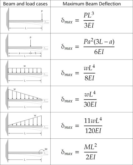
The Beam Stress and Deflection Calculator can handle various types of loading conditions, including point loads, uniformly distributed loads, and moments. Each type of load requires a different calculation approach, and the calculator takes this into account to provide accurate results. The calculator also considers the boundary conditions of the beam, such as simply supported, fixed, or cantilevered.
Material Properties and Beam Geometry
The calculator requires input of the beam's material properties, such as the Young's modulus, Poisson's ratio, and density. Additionally, the calculator needs information about the beam's geometry, including its length, width, and height! The calculator uses this information to determine the beam's cross-sectional area and moment of inertia, which are essential for calculating stress and deflection.
Calculation Methods and Formulas
The Beam Stress and Deflection Calculator uses various calculation methods and formulas to determine the stress and deflection of the beam. These include the beam theory, finite element method, and numerical integration. The calculator also uses formulas such as the flexure formula and shear formula to calculate the maximum stress and deflection.
Applications and Limitations
The Beam Stress and Deflection Calculator has various applications in civil engineering, mechanical engineering, and aerospace engineering. However, the calculator has limitations, such as assuming a linear elastic material behavior and neglecting non-linear effects. The calculator is also limited to static loading conditions and does not account for dynamic loading or fatigue.
| Property | Unit | Description |
|---|---|---|
| Young's Modulus | Pa | Material's stiffness |
| Poisson's Ratio | - | Material's lateral strain response |
| Cross-Sectional Area | m^2 | Beam's cross-sectional area |
| Moment of Inertia | m^4 | Beam's resistance to bending |
| Maximum Stress | Pa | Maximum stress in the beam |
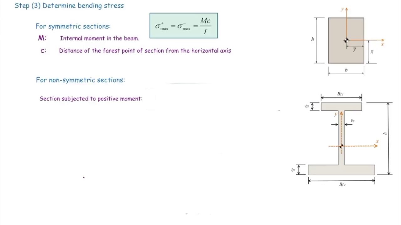
How do you calculate the stress of a beam?

To calculate the stress of a beam, you need to consider the load applied to it, the beam's material properties, and its cross-sectional area. The stress calculation involves determining the bending moment and shear forces acting on the beam, as well as the moment of inertia and section modulus of the beam's cross-section. This information is used to calculate the normal stress and shear stress at different points along the beam.
Understanding Beam Theory
Beam theory is based on the Euler-Bernoulli beam equation, which describes the relationship between the load, deflection, and stress in a beam. To calculate the stress of a beam, you need to understand the types of loads that can be applied, including point loads, uniformly distributed loads, and moments. The following steps are involved in calculating the stress of a beam:
- Determine the load applied to the beam and the beam's material properties, such as its Young's modulus and Poisson's ratio.
- Calculate the bending moment and shear forces acting on the beam using the load and beam's length.
- Determine the cross-sectional area and moment of inertia of the beam, which are used to calculate the section modulus.
Calculating Bending Moment and Shear Forces
The bending moment and shear forces are calculated using the load and beam's length. The bending moment is a measure of the torque applied to the beam, while the shear forces are a measure of the force applied parallel to the beam's cross-section. The following steps are involved in calculating the bending moment and shear forces:
- Determine the load applied to the beam and the beam's length.
- Calculate the bending moment using the load and beam's length.
- Calculate the shear forces using the load and beam's length.
Determining Cross-Sectional Area and Moment of Inertia
The cross-sectional area and moment of inertia are used to calculate the section modulus, which is a measure of the beam's resistance to bending. The cross-sectional area is a measure of the size of the beam's cross-section, while the moment of inertia is a measure of the distribution of the beam's cross-sectional area. The following steps are involved in determining the cross-sectional area and moment of inertia:
- Determine the beam's shape and dimensions.
- Calculate the cross-sectional area using the beam's shape and dimensions.
- Calculate the moment of inertia using the beam's shape and dimensions.
Calculating Normal Stress and Shear Stress
The normal stress and shear stress are calculated using the bending moment, shear forces, and section modulus. The normal stress is a measure of the tensile or compressive stress acting on the beam, while the shear stress is a measure of the force applied parallel to the beam's cross-section. The following steps are involved in calculating the normal stress and shear stress:
- Calculate the normal stress using the bending moment and section modulus.
- Calculate the shear stress using the shear forces and cross-sectional area.
- Determine the maximum stress acting on the beam.
Applying Safety Factors and Codes
The calculated stress values are compared to the material's yield strength and ultimate strength to determine the factor of safety. The factor of safety is a measure of the beam's ability to resist failure under load. The following steps are involved in applying safety factors and codes:
- Determine the material's yield strength and ultimate strength.
- Calculate the factor of safety using the calculated stress values and material's yield strength.
- Apply safety factors and codes to ensure the beam's safety and structurally sound design.
How do you calculate the deflection of a beam?
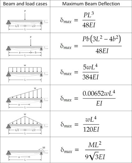
To calculate the deflection of a beam, you need to consider the beam's properties, such as its length, width, and height, as well as the load applied to it. The deflection of a beam can be calculated using various formulas and equations, depending on the type of load and the boundary conditions. The most common method is to use the beam deflection formula, which takes into account the moment of inertia of the beam's cross-sectional area and the Young's modulus of the material.
Understanding Beam Deflection Theory
The theory of beam deflection is based on the principle of superposition, which states that the deflection of a beam under a combination of loads is equal to the sum of the deflections under each individual load. To calculate the deflection, you need to know the load distribution along the beam and the support conditions. The deflection can be calculated using the following steps:
- Calculate the moment of inertia of the beam's cross-sectional area
- Determine the Young's modulus of the material
- Apply the beam deflection formula to calculate the deflection
Types of Beam Deflection
There are several types of beam deflection, including static deflection, dynamic deflection, and thermal deflection. Static deflection occurs when a beam is subjected to a constant load, while dynamic deflection occurs when the load is time-varying. Thermal deflection occurs when a beam is subjected to a temperature change. Each type of deflection requires a different approach to calculation, taking into account the beam's properties and the load characteristics.
- Static deflection is calculated using the beam deflection formula
- Dynamic deflection requires consideration of the beam's natural frequency and damping ratio
- Thermal deflection is calculated using the thermal expansion coefficient of the material
Beam Deflection Formulas
There are several formulas available to calculate the deflection of a beam, including the Euler-Bernoulli beam theory and the Timoshenko beam theory. The Euler-Bernoulli beam theory is a simplified model that assumes the beam is slender and the cross-sectional area is constant. The Timoshenko beam theory is a more advanced model that takes into account the shear deformation and rotary inertia of the beam.
- The Euler-Bernoulli beam theory is suitable for slender beams
- The Timoshenko beam theory is suitable for thick beams or beams with high shear loads
- Other beam deflection formulas are available for specific load cases and boundary conditions
Calculating Beam Deflection Using Numerical Methods
In addition to analytical methods, numerical methods can be used to calculate the deflection of a beam. Finite element methods and finite difference methods are popular numerical methods used to solve beam deflection problems. These methods involve discretizing the beam into smaller elements and solving the governing equations using numerical algorithms.
- Finite element methods are suitable for complex beam geometries and nonlinear materials
- Finite difference methods are suitable for simple beam geometries and linear materials
- Other numerical methods are available, such as the boundary element method and the meshless method
Applications of Beam Deflection Calculations
The calculation of beam deflection is critical in various engineering applications, including bridge design, building design, and machine design. The deflection of a beam can affect the stability and safety of a structure, and excessive deflection can lead to failure. Therefore, accurate calculations of beam deflection are essential to ensure the structural integrity of a building or machine.
- Bridge design requires accurate calculations of beam deflection to ensure stability and safety
- Building design requires consideration of beam deflection to ensure structural integrity
- Machine design requires accurate calculations of beam deflection to ensure optimal performance and reliability
How much deflection in a beam is acceptable?
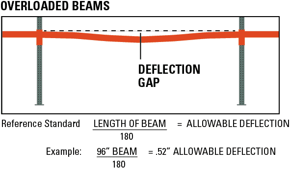
The amount of deflection in a beam that is considered acceptable depends on various factors, including the type of structure, the materials used, and the loads that the beam is expected to support. In general, the acceptable deflection is typically limited to a certain percentage of the beam's span length. For example, in building codes, the maximum allowable deflection is often limited to 1/360 of the span length for dead loads and 1/240 of the span length for live loads.
Acceptable Deflection Limits
The acceptable deflection limits for beams are typically specified in building codes and design standards. These limits are based on the safety and serviceability requirements of the structure. For example, the International Building Code (IBC) specifies that the maximum allowable deflection for beams supporting floors and roofs is 1/360 of the span length. The acceptable deflection limits may also depend on the type of occupation or use of the building, with more stringent limits applying to hospitals, schools, and other critical facilities.
- The type of structure and its occupancy can affect the acceptable deflection limits.
- The materials used for the beam, such as steel, concrete, or wood, can also impact the acceptable deflection limits.
- The loads that the beam is expected to support, including dead loads, live loads, and wind loads, can influence the acceptable deflection limits.
Deflection Calculation Methods
There are various methods for calculating the deflection of a beam, including the moment area method, the conjugate beam method, and the virtual work method. These methods can be used to determine the maximum deflection of a beam under different load conditions. The moment area method is a widely used method for calculating deflection, which involves calculating the moment and shear diagrams for the beam and then using these diagrams to calculate the deflection.
- The moment area method is a simple and accurate method for calculating deflection.
- The conjugate beam method is another method for calculating deflection, which involves creating a conjugate beam that is similar to the original beam but has a different support condition.
- The virtual work method is a more advanced method for calculating deflection, which involves using the principle of virtual work to calculate the deflection.
Factors Affecting Deflection
There are several factors that can affect the deflection of a beam, including the span length, the beam depth, the material properties, and the support conditions. For example, a longer span length can result in greater deflection, while a deeper beam can result in less deflection. The material properties, such as the modulus of elasticity and the moment of inertia, can also impact the deflection.
- The span length is a critical factor in determining the deflection of a beam.
- The beam depth can also impact the deflection, with deeper beams resulting in less deflection.
- The support conditions, including the restraints and connections, can influence the deflection of a beam.
Design Considerations
When designing a beam, it is essential to consider the deflection requirements and ensure that the beam is designed to meet these requirements. This may involve selecting a stronger material, increasing the beam depth, or providing additional support. The design should also take into account the loads that the beam is expected to support, including dead loads, live loads, and wind loads.
- Material selection is critical in designing a beam to meet deflection requirements.
- Beam sizing is also essential in ensuring that the beam can support the expected loads.
- Support conditions should be carefully considered to ensure that the beam is properly restrained and connected.
Deflection Measurement and Monitoring
In some cases, it may be necessary to measure and monitor the deflection of a beam over time. This can be done using various sensors and monitoring systems, such as strain gauges, accelerometers, and displacement sensors. The data collected from these sensors can be used to track the deflection of the beam and ensure that it remains within the acceptable limits.
- Strain gauges can be used to measure the strain and stress in a beam.
- Accelerometers can be used to measure the acceleration and vibration of a beam.
- Displacement sensors can be used to measure the displacement and deflection of a beam.
What is the allowable bending stress of a beam?
The allowable bending stress of a beam is the maximum stress that a beam can withstand without failing due to bending. This value is typically determined by the material properties of the beam, such as its yield strength and ultimate strength. The allowable bending stress is an important consideration in the design of beams, as it helps to ensure that the beam can support the expected loads without failing.
Calculating Allowable Bending Stress
Calculating the allowable bending stress of a beam involves using the beam's cross-sectional area, moment of inertia, and material properties. The calculation typically involves the following steps:
- Determine the beam's cross-sectional area and moment of inertia using the beam's dimensions and shape.
- Choose a safety factor to account for uncertainties in the material properties and loads.
- Use the beam's material properties, such as its yield strength and ultimate strength, to determine the allowable bending stress.
Factors Affecting Allowable Bending Stress
The allowable bending stress of a beam is affected by several factors, including the beam's material properties, cross-sectional area, and moment of inertia. Other factors, such as the beam's length, support conditions, and loads, can also impact the allowable bending stress. The following factors are particularly important:
- The beam's material properties, such as its yield strength and ultimate strength, which determine the allowable bending stress.
- The beam's cross-sectional area and moment of inertia, which affect the beam's stiffness and strength.
- The beam's length and support conditions, which can impact the beam's deflection and stress distribution.
Design Considerations for Allowable Bending Stress
When designing a beam, it is essential to consider the allowable bending stress to ensure that the beam can support the expected loads. The designer must consider the beam's material properties, cross-sectional area, and moment of inertia, as well as the loads and support conditions. The following design considerations are critical:
- Material selection, which involves choosing a material with suitable yield strength and ultimate strength.
- Cross-sectional area and moment of inertia, which must be sufficient to resist bending and deflection.
- Support conditions, which can impact the beam's stress distribution and deflection.
Testing and Verification of Allowable Bending Stress
Testing and verification of the allowable bending stress are crucial to ensure that the beam can support the expected loads. The testing process typically involves:
- Load testing, which involves applying a load to the beam and measuring its deflection and stress.
- Material testing, which involves determining the material properties, such as yield strength and ultimate strength.
- Finite element analysis, which involves using computer simulations to model the beam's behavior under various loads.
Applications of Allowable Bending Stress
The concept of allowable bending stress has numerous applications in various fields, including civil engineering, mechanical engineering, and aerospace engineering. The following applications are notable:
- Bridge design, which involves designing beams to support heavy loads and stresses.
- Building design, which involves designing beams to support gravity loads and lateral loads.
- Aircraft design, which involves designing beams to support aerodynamic loads and structural stresses.
Frequently Asked Questions (FAQs)
What is the Beam Stress and Deflection Calculator and how does it work?
The Beam Stress and Deflection Calculator is a tool designed to calculate the stress and deflection of a beam under various types of loads. It takes into account the beam's geometry, material properties, and the type and magnitude of the applied loads. The calculator uses mathematical formulas and algorithms to perform the calculations, providing accurate and reliable results. The calculator is commonly used by engineers and designers to analyze and design beams for various applications, such as buildings, bridges, and machines. By using the calculator, users can determine the maximum stress and deflection of the beam, ensuring that it can withstand the applied loads and operate safely.
What are the different types of loads that can be applied to a beam in the calculator?
The Beam Stress and Deflection Calculator allows users to apply various types of loads to the beam, including point loads, uniformly distributed loads, moment loads, and tapered loads. Each type of load is applied to the beam in a different way, and the calculator takes this into account when performing the calculations. For example, a point load is applied to a single point on the beam, while a uniformly distributed load is applied along the entire length of the beam. The calculator also allows users to apply multiple loads to the beam, making it possible to analyze complex loading scenarios. By considering the different types of loads, users can ensure that the beam is designed to withstand the actual loading conditions it will experience in service.
How does the calculator account for the material properties of the beam?
The Beam Stress and Deflection Calculator takes into account the material properties of the beam, including its Modulus of Elasticity, Poisson's Ratio, and yield strength. These properties are used to calculate the stress and deflection of the beam, and are essential for ensuring that the beam is designed to withstand the applied loads. The calculator allows users to select from a range of common materials, such as steel, aluminum, and wood, or to input their own custom material properties. By considering the material properties, users can ensure that the beam is designed to operate within its safe limits, and that it will not fail under load. The calculator also provides warnings and errors if the material properties are not suitable for the applied loads, helping users to identify potential design issues.
What are the limitations and assumptions of the Beam Stress and Deflection Calculator?
The Beam Stress and Deflection Calculator is a powerful tool, but it has some limitations and assumptions that users should be aware of. For example, the calculator assumes that the beam is straight and prismatic, and that the loads are applied in a static and linear manner. It also assumes that the material properties are constant and isotropic, and that the beam is simply supported or fixed at its ends. In addition, the calculator does not account for dynamic loads, non-linear materials, or complex geometries, which can affect the accuracy of the results. Users should carefully review the assumptions and limitations of the calculator to ensure that it is suitable for their specific design application, and to validate the results using experimental testing or finite element analysis if necessary. By understanding the limitations and assumptions, users can use the calculator with confidence, and ensure that their designs are safe and reliable.
Deja una respuesta
Entradas Relacionadas