
Barlow's Formula, Calculator and MAOP Design Factors
Barlow's Formula is a widely used calculation in the pipeline industry to determine the maximum allowable operating pressure (MAOP) of a pipe. The formula takes into account the pipe's dimensions, material strength, and corrosion allowance to provide a safe and reliable operating pressure. A Barlow's Formula calculator can simplify this process, allowing engineers to quickly and accurately determine the MAOP and design factors for various pipeline scenarios, ensuring the safe and efficient transportation of fluids and gases through pipelines. This calculation is crucial for pipeline design and operation.
- Understanding Barlow's Formula, Calculator, and MAOP Design Factors
- What is the Barlow's formula for design factor?
- What is the formula for the Barlow equation?
- What are the assumptions of Barlow's formula?
- What is the formula for pressure design?
-
Frequently Asked Questions (FAQs)
- ¿Qué es la fórmula de Barlow y cómo se utiliza en el diseño de tuberías?
- ¿Cómo funciona el calculador de la fórmula de Barlow y qué parámetros se necesitan para calcular la presión máxima permitida?
- ¿Qué es el MAOP (Presión Máxima de Operación) y cómo se relaciona con la fórmula de Barlow y el diseño de tuberías?
- ¿Cuáles son los factores de diseño más importantes que se deben considerar al utilizar la fórmula de Barlow y el MAOP para diseñar tuberías?
Understanding Barlow's Formula, Calculator, and MAOP Design Factors
Barlow's formula is a widely used equation in the field of pipeline engineering to calculate the maximum allowable operating pressure (MAOP) of a pipeline. The formula takes into account the pipe's diameter, wall thickness, and material properties to determine the maximum safe operating pressure. The Barlow's formula calculator is a tool used to simplify the calculation process and provide accurate results. The MAOP design factors are critical in ensuring the safe operation of pipelines, as they help to prevent pipeline failures and minimize the risk of accidents.
Introduction to Barlow's Formula
Barlow's formula is a mathematical equation that calculates the maximum allowable operating pressure (MAOP) of a pipeline based on its diameter, wall thickness, and material properties. The formula is as follows: P = (2 ST t) / D, where P is the maximum allowable operating pressure, ST is the specified minimum yield strength of the pipe material, t is the nominal wall thickness, and D is the outside diameter of the pipe. The formula is widely used in the pipeline industry to ensure the safe operation of pipelines.
Barlow's Formula Calculator
The Barlow's formula calculator is a tool used to simplify the calculation process and provide accurate results. The calculator takes into account the pipe's diameter, wall thickness, and material properties to calculate the maximum allowable operating pressure (MAOP). The calculator is commonly used by pipeline engineers and operators to ensure the safe operation of pipelines. The calculator can be used to calculate the MAOP for various pipeline scenarios, including gas transmission pipelines, oil pipelines, and water pipelines.
MAOP Design Factors
The MAOP design factors are critical in ensuring the safe operation of pipelines. The design factors take into account various parameters, including the pipe's diameter, wall thickness, material properties, and operating conditions. The design factors are used to calculate the maximum allowable operating pressure (MAOP) of a pipeline and to ensure that the pipeline is operated within safe limits. The MAOP design factors include the design factor, corrosion allowance, and construction factor.
Factors Affecting MAOP
Several factors can affect the maximum allowable operating pressure (MAOP) of a pipeline, including the pipe's diameter, wall thickness, material properties, and operating conditions. The pipe diameter and wall thickness are critical factors, as they affect the pipe's burst pressure and collapse pressure. The material properties, such as the yield strength and tensile strength, also affect the MAOP. Additionally, operating conditions, such as temperature and pressure, can also impact the MAOP.
Importance of MAOP in Pipeline Design
The maximum allowable operating pressure (MAOP) is a critical parameter in pipeline design, as it ensures the safe operation of pipelines. The MAOP is used to determine the design pressure of a pipeline, which is the maximum pressure at which the pipeline can be operated safely. The MAOP is also used to determine the wall thickness and material properties required for the pipeline. The following table summarizes the key factors affecting the MAOP:
| Factor | Description |
|---|---|
| Pipe Diameter | Affects the pipe's burst pressure and collapse pressure |
| Wall Thickness | Affects the pipe's burst pressure and collapse pressure |
| Material Properties | Affects the pipe's yield strength and tensile strength |
| Operating Conditions | Affects the pipe's temperature and pressure |
| Design Factor | Affects the pipe's maximum allowable operating pressure |
What is the Barlow's formula for design factor?
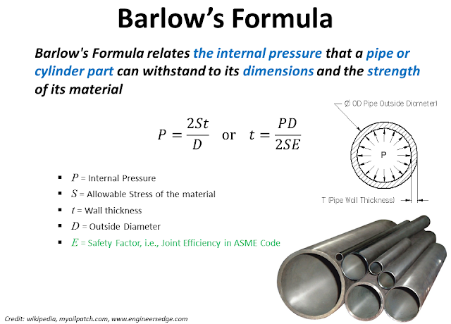
The Barlow's formula for design factor is a mathematical equation used to calculate the wall thickness of a pipe based on its internal pressure, yield strength, and corrosion allowance. The formula is: t = (P D) / (2 S E), where t is the wall thickness, P is the internal pressure, D is the outside diameter, S is the yield strength, and E is the joint efficiency. This formula is widely used in the petrochemical and power generation industries to ensure the integrity of pipes and tubes.
Introduction to Barlow's Formula
Barlow's formula is a fundamental equation in mechanical engineering that helps designers calculate the required wall thickness of a pipe to withstand internal pressure. The formula takes into account the material properties of the pipe, such as its yield strength and corrosion allowance, as well as the operating conditions, including temperature and pressure. To apply Barlow's formula, designers must consider the following factors:
- The internal pressure of the pipe, which is the primary load that the pipe must withstand.
- The yield strength of the pipe material, which determines its ability to resist deformation.
- The corrosion allowance, which is the amount of material loss due to corrosion that the pipe can tolerate.
Derivation of Barlow's Formula
Barlow's formula is derived from the theory of elasticity and the principle of conservation of energy. The formula is based on the equilibrium of forces and moments acting on a circular pipe. The derivation of Barlow's formula involves the following steps:
- Assuming a thin-walled pipe with a circular cross-section.
- Applying the equilibrium equations to the pipe, including the force balance and moment balance.
- Using the constitutive equation for the pipe material to relate the stress and strain.
Applications of Barlow's Formula
Barlow's formula has widespread applications in mechanical engineering, including the design of pipes, tubes, and pressure vessels. The formula is used to calculate the required wall thickness of a pipe to ensure its structural integrity and safety. Some of the key applications of Barlow's formula include:
- Power generation, where pipes and tubes are used to transport high-pressure and high-temperature fluids.
- Petroleum refining, where pipes and tubes are used to transport corrosive and flammable fluids.
- Chemical processing, where pipes and tubes are used to transport toxic and reactive chemicals.
Limits of Barlow's Formula
While Barlow's formula is a powerful tool for designing pipes and tubes, it has several limitations. The formula assumes a thin-walled pipe with a circular cross-section, which may not always be the case. Additionally, the formula does not account for external loads, such as bending and torsion, which can affect the structural integrity of the pipe. Some of the key limitations of Barlow's formula include:
- Assumes a thin-walled pipe, which may not be accurate for thick-walled pipes.
- Does not account for external loads, which can affect the structural integrity of the pipe.
- Assumes a circular cross-section, which may not be accurate for non-circular pipes.
Alternatives to Barlow's Formula
There are several alternatives to Barlow's formula that can be used to calculate the required wall thickness of a pipe. Some of these alternatives include:
- ASME Boiler and Pressure Vessel Code, which provides a set of design rules for pressure vessels.
- API 5L, which provides a set of design rules for line pipes.
- Finite element analysis, which can be used to simulate the behavior of a pipe under various loads and conditions.
What is the formula for the Barlow equation?
The formula for the Barlow equation is σ = (σ_y A) / (A - σ_y (L_e / E)), where σ is the stress, σ_y is the yield strength, A is the cross-sectional area, L_e is the effective length, and E is the modulus of elasticity. This equation is used to calculate the stress in a column under compressive load.
Understanding the Barlow Equation
The Barlow equation is a fundamental concept in mechanics of materials and is used to determine the stress in a column under compressive load. To apply this equation, one needs to understand the parameters involved, such as yield strength, cross-sectional area, effective length, and modulus of elasticity. The following are the key points to consider:
- The yield strength is the stress at which the material begins to deform plastically.
- The cross-sectional area is the area of the column perpendicular to the load direction.
- The effective length is the length of the column that is subjected to load.
Applications of the Barlow Equation
The Barlow equation has numerous applications in engineering design, particularly in the design of columns and compression members. The equation is used to determine the stress in a column under compressive load, which is essential for ensuring the structural integrity of the member. Some of the key applications include:
- Building design: The Barlow equation is used to design columns and beams in buildings to ensure they can withstand compressive loads.
- Bridge design: The equation is used to design bridge piers and abutments to resist compressive forces.
- Machine design: The Barlow equation is used to design machine components, such as shafts and gears, to withstand compressive loads.
Assumptions of the Barlow Equation
The Barlow equation is based on several assumptions, including the assumption of a prismatic column with a uniform cross-sectional area. The equation also assumes that the material is homogeneous and isotropic, and that the load is axially applied. The following are some of the key assumptions:
- The column is prismatic, with a uniform cross-sectional area.
- The material is homogeneous and isotropic.
- The load is axially applied, with no bending or torsion.
Limits of the Barlow Equation
The Barlow equation has several limits, including the limit of validity for slender columns. The equation is also limited by the assumption of a linear elastic material, which may not be valid for all materials. Some of the key limits include:
- The column must be slender, with a length that is greater than 4-6 times the least radius of gyration.
- The material must be linear elastic, with a stress-strain curve that is linear up to yield.
- The load must be axially applied, with no bending or torsion.
Extensions of the Barlow Equation
The Barlow equation has been extended to include various effects, such as bending and torsion. These extensions allow the equation to be used for a wider range of applications, including the design of beams and shafts. Some of the key extensions include:
- Bending: The equation can be modified to include bending effects, allowing it to be used for beam design.
- Torsion: The equation can be extended to include torsion effects, allowing it to be used for shaft design.
- Nonlinear materials: The equation can be modified to include nonlinear material effects, allowing it to be used for materials with nonlinear stress-strain curves.
What are the assumptions of Barlow's formula?

The assumptions of Barlow's formula are based on several key principles. Barlow's formula is used to calculate the wall thickness of a pipe based on the internal pressure and the yield strength of the material. The formula assumes that the pipe is cylindrical in shape and that the internal pressure is uniform along the length of the pipe. Additionally, the formula assumes that the material is homogeneous and isotropic, meaning that its properties are the same in all directions.
Assumptions of Material Properties
The assumptions of Barlow's formula include the material properties of the pipe, such as its yield strength and ultimate tensile strength. These properties are assumed to be constant and uniform throughout the pipe. The formula also assumes that the material is ductile, meaning that it can withstand significant deformation without fracturing.
- The material is homogeneous and isotropic
- The yield strength and ultimate tensile strength are constant and uniform throughout the pipe
- The material is ductile and can withstand significant deformation without fracturing
Assumptions of Pipe Geometry
The assumptions of Barlow's formula also include the geometry of the pipe, such as its diameter and wall thickness. The formula assumes that the pipe is cylindrical in shape and that the internal pressure is uniform along the length of the pipe. The formula also assumes that the pipe is straight and that there are no bends or curves.
- The pipe is cylindrical in shape
- The internal pressure is uniform along the length of the pipe
- The pipe is straight and there are no bends or curves
Assumptions of Internal Pressure
The assumptions of Barlow's formula include the internal pressure of the pipe, which is assumed to be uniform and constant. The formula also assumes that the internal pressure is static, meaning that it does not change over time. The formula does not account for dynamic or time-varying internal pressures.
- The internal pressure is uniform and constant
- The internal pressure is static, meaning that it does not change over time
- The formula does not account for dynamic or time-varying internal pressures
The assumptions of Barlow's formula include the failure modes of the pipe, which are assumed to be ductile and tensile. The formula assumes that the pipe will fail due to excessive deformation or tensile stress, rather than brittle fracture or other failure modes. The formula also assumes that the pipe will not experience corrosion or erosion.
- The pipe will fail due to excessive deformation or tensile stress
- The pipe will not experience corrosion or erosion
- The formula assumes that the failure mode is ductile and tensile
Assumptions of Design Factors
The assumptions of Barlow's formula include the design factors of the pipe, such as the safety factor and the factor of safety. The formula assumes that the design factors are constant and uniform, and that they are based on the material properties and internal pressure of the pipe. The formula also assumes that the design factors are conservative, meaning that they provide a margin of safety against failure.
- The design factors are constant and uniform
- The design factors are based on the material properties and internal pressure of the pipe
- The design factors are conservative, meaning that they provide a margin of safety against failure
What is the formula for pressure design?
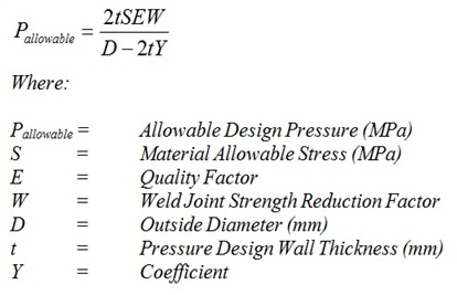
The formula for pressure design is Pressure (P) = Force (F) / Area (A), which is commonly expressed as P = F/A. This formula is a fundamental concept in physics and engineering, and it is widely used to calculate the pressure exerted on an object or a surface. The formula can be applied to various fields, including mechanical engineering, aerospace engineering, and civil engineering.
Understanding the Formula Components
The pressure design formula consists of three main components: pressure (P), force (F), and area (A). Understanding these components is crucial to apply the formula correctly. The key aspects of these components are:
- The pressure (P) is the result of the force applied to a specific area, and it is typically measured in pascals (Pa) or pounds per square inch (psi).
- The force (F) is the push or pull that is applied to an object or a surface, and it is typically measured in newtons (N) or pounds (lb).
- The area (A) is the surface over which the force is applied, and it is typically measured in square meters (m²) or square inches (in²).
Applications of Pressure Design
The pressure design formula has numerous applications in various fields, including engineering, architecture, and physics. Some of the key applications are:
- Pipeline design: The pressure design formula is used to calculate the pressure exerted on pipes and tubes, ensuring that they can withstand the internal pressure and external loads.
- Building design: The formula is used to calculate the pressure exerted on buildings and structures, ensuring that they can withstand wind loads and earthquake forces.
- Vehicle design: The pressure design formula is used to calculate the pressure exerted on vehicles, such as aircraft and spacecraft, ensuring that they can withstand aerodynamic forces and thermal stresses.
Importance of Pressure Design
Pressure design is a critical aspect of engineering and architecture, as it ensures that structures and objects can withstand various loads and stresses. The importance of pressure design can be seen in:
- Safety: Pressure design helps to ensure that structures and objects are safe for use, reducing the risk of accidents and injuries.
- Performance: Pressure design helps to optimize the performance of structures and objects, ensuring that they can function effectively and efficiently.
- Cost-effectiveness: Pressure design can help to reduce costs associated with repairs and maintenance, as well as minimize the risk of equipment failure.
Pressure Design Considerations
When applying the pressure design formula, there are several considerations that must be taken into account, including:
- Material properties: The material properties of the object or structure, such as density and elasticity, can affect the pressure design calculations.
- Boundary conditions: The boundary conditions of the object or structure, such as supports and constraints, can affect the pressure design calculations.
- Load combinations: The load combinations that the object or structure is subjected to, such as static and dynamic loads, can affect the pressure design calculations.
Pressure Design Tools and Software
There are various tools and software available to aid in pressure design calculations, including:
- Finite element analysis (FEA) software: FEA software, such as ANSYS and ABAQUS, can be used to simulate and analyze the behavior of complex structures and objects under various loads.
- Computer-aided design (CAD) software: CAD software, such as AUTOCAD and SOLIDWORKS, can be used to create and analyze 2D and 3D models of structures and objects.
- Spreadsheet software: Spreadsheet software, such as EXCEL, can be used to perform pressure design calculations and analyze data.
Frequently Asked Questions (FAQs)
¿Qué es la fórmula de Barlow y cómo se utiliza en el diseño de tuberías?
La fórmula de Barlow es una ecuación utilizada para calcular la presión máxima permitida en una tubería, teniendo en cuenta factores como el diámetro interno, el grosor de la pared y las propiedades mecánicas del material de la tubería. La fórmula es ampliamente utilizada en la industria del petróleo y el gas para diseñar tuberías que puedan soportar las presiones y temperaturas extremas asociadas con la producción y transporte de hidrocarburos. La fórmula de Barlow se basa en la teoría de la resistencia de materiales y la mecánica de fluidos, y proporciona una herramienta valiosa para los ingenieros que diseñan y operan sistemas de tuberías. Al utilizar la fórmula de Barlow, los ingenieros pueden determinar la presión máxima permitida en una tubería y asegurarse de que el sistema sea seguro y eficiente.
¿Cómo funciona el calculador de la fórmula de Barlow y qué parámetros se necesitan para calcular la presión máxima permitida?
El calculador de la fórmula de Barlow es una herramienta básica que se utiliza para calcular la presión máxima permitida en una tubería, utilizando la fórmula de Barlow. Para calcular la presión máxima permitida, se necesitan varios parámetros, incluyendo el diámetro interno de la tubería, el grosor de la pared, la resistencia a la tracción del material de la tubería y la temperatura de operación. El calculador también puede requerir información adicional, como la reature de diseño y el factor de seguridad. Una vez que se ingresan estos parámetros, el calculador puede proporcionar la presión máxima permitida en la tubería, lo que permite a los ingenieros diseñar un sistema de tuberías que sea seguro y eficiente. La precisión del calculador depende de la exactitud de los parámetros de entrada, por lo que es importante utilizar valores precisos y confiables.
¿Qué es el MAOP (Presión Máxima de Operación) y cómo se relaciona con la fórmula de Barlow y el diseño de tuberías?
El MAOP (Presión Máxima de Operación) es el valor máximo de presión al que se permite operar una tubería, y se determina utilizando la fórmula de Barlow y otros factores de diseño. La fórmula de Barlow se utiliza para calcular la presión máxima permitida en una tubería, y el MAOP se establece en un valor inferior a esta presión para proporcionar un factor de seguridad. El MAOP se relaciona con la fórmula de Barlow porque se utiliza para determinar la presión máxima permitida en una tubería, y se utiliza como referencia para diseñar y operar sistemas de tuberías. El MAOP también se utiliza para determinar la Clazz de una tubería, que es una medida de la resistencia de la tubería a la presión. Al establecer un MAOP, los ingenieros pueden asegurarse de que el sistema de tuberías sea seguro y eficiente, y que se cumplan los estándares de seguridad y regulaciones.
¿Cuáles son los factores de diseño más importantes que se deben considerar al utilizar la fórmula de Barlow y el MAOP para diseñar tuberías?
Al diseñar tuberías utilizando la fórmula de Barlow y el MAOP, hay varios factores de diseño que se deben considerar para asegurarse de que el sistema sea seguro y eficiente. Algunos de los factores más importantes incluyen el material de la tubería, el diámetro interno y el grosor de la pared, la temperatura de operación y la presión máxima permitida. También se deben considerar factores como la corrosión, la erosión y la fatiga, que pueden afectar la resistencia y la seguridad de la tubería. Además, se deben cumplir los estándares de seguridad y regulaciones, como los establecidos por la ASME (Sociedad Americana de Ingenieros Mecánicos) y la API (Instituto Americano del Petróleo). Al considerar estos factores de diseño, los ingenieros pueden crear un sistema de tuberías que sea seguro, eficiente y que cumpla con los estándares y regulaciones aplicables. La experiencia y el conocimiento de los ingenieros también son fundamentales para diseñar un sistema de tuberías que sea seguro y eficiente.
Deja una respuesta
Entradas Relacionadas