
Composite Position Tolerance GD&T Calculator for Internal FOS
The Composite Position Tolerance GD&T Calculator for Internal FOS is a specialized tool used to calculate the position tolerance of features within a part or assembly. Geometric Dimensioning and Tolerancing (GD&T) is a critical aspect of engineering design, ensuring that parts fit together properly and function as intended. This calculator simplifies the process of calculating position tolerances for internal features, taking into account the complexities of composite position tolerancing and the Free State Orientation (FOS) of parts, enabling designers to optimize their designs with precision and accuracy. It streamlines the design process and reduces errors.
- Composite Position Tolerance GD&T Calculator for Internal FOS: A Comprehensive Guide
-
Understanding the Composite Position Tolerance GD&T Calculator for Internal FOS
- What is Composite Position Tolerance in GD&T?
- How to Use the Composite Position Tolerance GD&T Calculator for Internal FOS
- Benefits of Using the Composite Position Tolerance GD&T Calculator for Internal FOS
- Common Applications of the Composite Position Tolerance GD&T Calculator for Internal FOS
- Best Practices for Using the Composite Position Tolerance GD&T Calculator for Internal FOS
-
Frequently Asked Questions (FAQs)
- What is the Composite Position Tolerance GD&T Calculator for Internal FOS?
- How does the Composite Position Tolerance GD&T Calculator for Internal FOS work?
- What are the benefits of using the Composite Position Tolerance GD&T Calculator for Internal FOS?
- How can I get started with the Composite Position Tolerance GD&T Calculator for Internal FOS?
Composite Position Tolerance GD&T Calculator for Internal FOS: A Comprehensive Guide
The Composite Position Tolerance GD&T Calculator for Internal FOS is a specialized tool used in the field of Geometric Dimensioning and Tolerancing (GD&T) to calculate the position tolerance of internal features of a part. This calculator is essential in ensuring that the parts are manufactured within the specified tolerance limits, which is critical in maintaining the overall quality and performance of the final product.
Introduction to Composite Position Tolerance
Composite position tolerance is a type of GD&T tolerance that combines the position tolerance of two or more features. This type of tolerance is used to control the location and orientation of features such as holes, slots, and surfaces. The composite position tolerance calculator takes into account the individual tolerances of each feature and calculates the overall tolerance of the part.
How to Use the Composite Position Tolerance Calculator
To use the composite position tolerance calculator, the user must input the individual tolerances of each feature, as well as the datums and references used to establish the coordinate system. The calculator then uses algorithms and formulas to calculate the composite position tolerance. The result is a tolerance value that represents the maximum allowable deviation from the nominal position of the feature.
Benefits of Using the Composite Position Tolerance Calculator
The composite position tolerance calculator offers several benefits, including improved accuracy, reduced errors, and increased efficiency. By using this calculator, manufacturers can ensure that their parts are produced within the specified tolerance limits, which reduces the risk of rework and scrap. Additionally, the calculator helps to streamline the design and manufacturing process, which can lead to cost savings and improved productivity.
Key Concepts in Composite Position Tolerance Calculation
The following table summarizes the key concepts involved in composite position tolerance calculation:
| Concept | Description |
|---|---|
| Position Tolerance | The maximum allowable deviation from the nominal position of a feature. |
| Composite Tolerance | The overall tolerance of a part, which is calculated by combining the individual tolerances of each feature. |
| Datum | A reference point or surface used to establish the coordinate system. |
| Reference | A feature or surface used to establish the orientation of a part. |
| Coordinate System | A system used to locate and orient features in 3D space. |
Common Applications of Composite Position Tolerance Calculators
Composite position tolerance calculators are commonly used in various industries, including aerospace, automotive, and medical devices. These calculators are used to ensure that parts are manufactured within the specified tolerance limits, which is critical in maintaining the overall quality and performance of the final product. Additionally, these calculators are used to validate and verify the design and manufacturing process, which helps to reduce errors and improve efficiency.
Understanding the Composite Position Tolerance GD&T Calculator for Internal FOS
The Composite Position Tolerance GD&T Calculator for Internal FOS is a complex tool used in geometric dimensioning and tolerancing (GD&T) to calculate the position tolerance of features of size (FOS) within a part or assembly. This calculator is essential in ensuring that the parts or assemblies meet the required specifications and tolerances. The calculator takes into account various factors such as the datum features, tolerance zones, and material conditions to determine the allowable variation in the position of the FOS.
What is Composite Position Tolerance in GD&T?
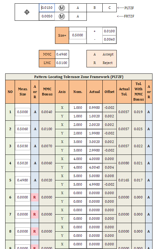
Composite position tolerance in GD&T refers to the combination of two or more position tolerances that are applied to a single feature of size (FOS). This type of tolerance is used to control the location and orientation of the FOS within a part or assembly. The composite position tolerance is specified using a tolerance zone that is defined by two or more datum features. The tolerance zone is the three-dimensional space within which the FOS must be contained. The composite position tolerance is calculated using a calculator that takes into account the datum features, tolerance zones, and material conditions.
How to Use the Composite Position Tolerance GD&T Calculator for Internal FOS
Using the Composite Position Tolerance GD&T Calculator for Internal FOS requires a good understanding of GD&T principles and concepts. The calculator is typically used in conjunction with a drawing or model of the part or assembly. The user must input the relevant information such as the datum features, tolerance zones, and material conditions. The calculator then calculates the composite position tolerance and displays the results. The user can then use the results to verify that the part or assembly meets the required specifications and tolerances. The calculator is available in various forms such as software programs, spreadsheets, and online tools.
Benefits of Using the Composite Position Tolerance GD&T Calculator for Internal FOS
Using the Composite Position Tolerance GD&T Calculator for Internal FOS offers several benefits. One of the main advantages is that it ensures that the parts or assemblies meet the required specifications and tolerances. The calculator reduces the risk of errors and misinterpretations of the GD&T specifications. The calculator also saves time and increases productivity by automating the calculation process. Additionally, the calculator provides a consistent and reliable method of calculating the composite position tolerance, which is essential in ensuring the quality and reliability of the parts or assemblies.
Common Applications of the Composite Position Tolerance GD&T Calculator for Internal FOS
The Composite Position Tolerance GD&T Calculator for Internal FOS has various applications in different industries such as aerospace, automotive, medical, and consumer products. The calculator is commonly used in the design and manufacturing of complex parts and assemblies such as engines, gearboxes, and mechanisms. The calculator is also used in the inspection and verification of parts and assemblies to ensure that they meet the required specifications and tolerances. The calculator is essential in ensuring the quality and reliability of the parts or assemblies, which is critical in many industries.
Best Practices for Using the Composite Position Tolerance GD&T Calculator for Internal FOS
When using the Composite Position Tolerance GD&T Calculator for Internal FOS, it is important to follow best practices to ensure accurate and reliable results. One of the key best practices is to understand the GD&T principles and concepts and to use the calculator in conjunction with a drawing or model of the part or assembly. Another important best practice is to input the relevant information accurately and to verify the results. The user should also use the calculator in accordance with the relevant standards and specifications such as ASME or ISO. By following these best practices, the user can ensure that the calculator is used effectively and that the results are accurate and reliable. The user should also consider the material conditions and datum features when using the calculator to ensure that the results are valid and reliable.
Frequently Asked Questions (FAQs)
What is the Composite Position Tolerance GD&T Calculator for Internal FOS?
The Composite Position Tolerance GD&T Calculator for Internal FOS is a software tool designed to help engineers and manufacturers calculate the position tolerance of internal features of a part, taking into account the geometric dimensions and tolerances (GD&T). This calculator is specifically designed for internal features, such as holes, grooves, and pockets, and uses the Feature of Size (FOS) concept to determine the position tolerance. The calculator uses complex algorithms to analyze the GD&T specifications and calculate the position tolerance, allowing users to ensure that their parts meet the required tolerances and specifications. By using this calculator, users can improve the accuracy of their designs and manufacturing processes, and reduce errors and rework.
How does the Composite Position Tolerance GD&T Calculator for Internal FOS work?
The Composite Position Tolerance GD&T Calculator for Internal FOS works by analyzing the GD&T specifications for the internal feature, including the datum features, tolerances, and material conditions. The calculator then uses advanced mathematical models to simulate the manufacturing process and calculate the position tolerance of the feature. The calculator takes into account variations in size, orientation, and location of the feature, as well as surface roughness and other factors that can affect the position tolerance. The calculator provides a detailed report of the calculation, including the position tolerance, tolerance zone, and other relevant information. This report can be used to verify the design, optimize the manufacturing process, and ensure compliance with industry standards and regulations. By using this calculator, users can streamline their design and manufacturing processes, and improve the overall quality of their parts.
What are the benefits of using the Composite Position Tolerance GD&T Calculator for Internal FOS?
The benefits of using the Composite Position Tolerance GD&T Calculator for Internal FOS are numerous. One of the main benefits is improved accuracy, as the calculator provides a highly accurate calculation of the position tolerance, taking into account all the relevant GD&T specifications and manufacturing factors. Another benefit is reduced errors, as the calculator helps users to identify and correct errors in the design and manufacturing process, reducing the need for rework and scrap. The calculator also saves time, as it automates the calculation process, allowing users to focus on other tasks. Additionally, the calculator improves collaboration, as it provides a common language and framework for designers, manufacturers, and inspectors to communicate and work together. By using this calculator, users can improve the overall quality of their parts, reduce costs, and increase productivity.
How can I get started with the Composite Position Tolerance GD&T Calculator for Internal FOS?
To get started with the Composite Position Tolerance GD&T Calculator for Internal FOS, users can download the software from the manufacturer's website or purchase a license from an authorized reseller. Once the software is installed, users can launch the calculator and enter the GD&T specifications for the internal feature, including the datum features, tolerances, and material conditions. The calculator will then guide the user through the calculation process, providing clear instructions and helpful tips to ensure that the user understands the results. Users can also access online resources, such as tutorials, webinars, and user forums, to learn more about the calculator and get support from other users and experts. By following these steps, users can quickly get started with the calculator and start achieving the benefits of improved accuracy, reduced errors, and increased productivity.
Deja una respuesta
Entradas Relacionadas