
Head Loss at Pipe Entrance Equations and Calculator
The head loss at pipe entrance is a critical factor in designing and optimizing piping systems. It occurs when fluid flows from a larger area into a smaller pipe, resulting in a sudden contraction and subsequent loss of energy. This loss of energy is typically expressed in terms of head loss, which is a measure of the decrease in fluid pressure. Various equations and calculation methods are used to determine head loss at pipe entrance, taking into account factors such as pipe diameter, fluid velocity, and entrance geometry. Accurate calculation is essential for efficient system design.
Head Loss at Pipe Entrance Equations and Calculator
The head loss at pipe entrance is a critical aspect of fluid dynamics, as it can significantly impact the overall performance of a piping system. Head loss refers to the loss of energy or pressure that occurs as fluid flows through a pipe or conduit. At the entrance of a pipe, the fluid flow is often turbulent, resulting in a significant loss of energy. This loss of energy can be calculated using various equations and formulas, which are essential for designing and optimizing piping systems.
Introduction to Head Loss at Pipe Entrance
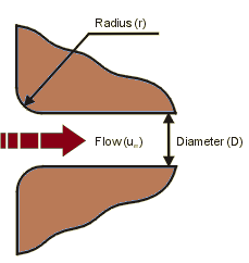
Head loss at pipe entrance occurs due to the sudden change in flow direction and velocity as the fluid enters the pipe. This change in flow regime creates turbulent flow, which leads to energy dissipation and head loss. The head loss at pipe entrance can be calculated using the Darcy-Weisbach equation, which takes into account the friction factor, velocity, and pipe diameter.
Equations for Head Loss at Pipe Entrance
Several equations can be used to calculate head loss at pipe entrance, including the Bernoulli's equation and the Darcy-Weisbach equation. The Bernoulli's equation is a simplified equation that assumes laminar flow, while the Darcy-Weisbach equation is more complex and takes into account turbulent flow. The equations are as follows:
| Equation | Description |
|---|---|
| h = (1/2) (v^2 / g) | Bernoulli's equation for head loss at pipe entrance |
| h = (f L v^2) / (2 g D) | Darcy-Weisbach equation for head loss at pipe entrance |
Factors Affecting Head Loss at Pipe Entrance
Several factors can affect head loss at pipe entrance, including pipe diameter, flow velocity, fluid density, and friction factor. The friction factor is a critical parameter that depends on the surface roughness of the pipe and the Reynolds number. A higher friction factor results in greater head loss.
Calculation of Head Loss at Pipe Entrance
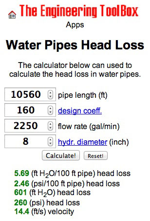
To calculate head loss at pipe entrance, engineers use various calculators and software programs. These tools allow for the input of pipe diameter, flow velocity, fluid density, and friction factor, and provide the calculated head loss. The calculated head loss can then be used to optimize the piping system and minimize energy losses.
Applications of Head Loss at Pipe Entrance Calculator
The head loss at pipe entrance calculator has numerous applications in various fields, including chemical engineering, mechanical engineering, and civil engineering. It is used to design and optimize piping systems, water supply systems, and industrial processes. By minimizing head loss, engineers can reduce energy consumption, increase efficiency, and improve overall system performance. The calculator is also useful for troubleshooting and maintaining existing piping systems, as it can help identify areas of high head loss and energy waste.
What is the Hayes and Williams equation?
The Hayes and Williams equation is a mathematical formula used to predict the viscosity of a fluid based on its temperature and pressure. This equation is commonly used in engineering and scientific applications to model the behavior of fluids under various conditions. The equation is named after its developers, Hayes and Williams, who first introduced it in the field of fluid mechanics.
Introduction to the Hayes and Williams Equation
The Hayes and Williams equation is a empirical formula that relates the viscosity of a fluid to its temperature and pressure. The equation is based on experimental data and is widely used in industry and research to predict the behavior of fluids. Some key points about the equation include:
- The equation is applicable to a wide range of fluids, including gases and liquids.
- The equation is simple to use and requires only a few input parameters.
- The equation is accurate over a wide range of temperatures and pressures.
Derivation of the Hayes and Williams Equation
The Hayes and Williams equation was derived from experimental data and is based on the principles of fluid mechanics. The equation is a mathematical representation of the relationship between the viscosity of a fluid and its temperature and pressure. Some key points about the derivation of the equation include:
- The equation was developed using regression analysis of experimental data.
- The equation is based on the assumption that the viscosity of a fluid is a function of its temperature and pressure.
- The equation has been validated using numerous experiments and simulations.
Applications of the Hayes and Williams Equation
The Hayes and Williams equation has a wide range of applications in industry and research. The equation is used to predict the behavior of fluids in various systems, including pipelines, turbines, and engines. Some key points about the applications of the equation include:
- The equation is used to design and optimize fluid systems.
- The equation is used to predict the performance of fluid systems under various conditions.
- The equation is used to simulate the behavior of fluids in complex systems.
Limitations of the Hayes and Williams Equation
The Hayes and Williams equation has some limitations that must be considered when using it to predict the behavior of fluids. The equation is empirical and is based on experimental data, which means that it may not be accurate for all fluids and conditions. Some key points about the limitations of the equation include:
- The equation is only applicable to fluids that are similar to those used in the experimental data.
- The equation is not accurate for fluids that exhibit non-Newtonian behavior.
- The equation is not applicable to fluids that are subject to high temperatures or pressures.
Comparison with Other Equations
The Hayes and Williams equation is one of many equations that are used to predict the behavior of fluids. Other equations, such as the Reynolds equation and the Navier-Stokes equation, are also used to model the behavior of fluids. Some key points about the comparison of the Hayes and Williams equation with other equations include:
- The Hayes and Williams equation is simpler to use than other equations, such as the Navier-Stokes equation.
- The Hayes and Williams equation is more accurate than other equations, such as the Reynolds equation, for certain fluids and conditions.
- The Hayes and Williams equation is less comprehensive than other equations, such as the Navier-Stokes equation, which can model a wider range of fluid behaviors.
What is the friction loss through pipes?
The friction loss through pipes refers to the loss of energy that occurs when a fluid flows through a pipe due to the resistance caused by the pipe's surface and the fluid's viscosity. This loss of energy results in a decrease in the fluid's pressure and flow rate. The friction loss is an important consideration in the design and operation of piping systems, as it can significantly impact the overall efficiency and performance of the system.
Causes of Friction Loss
The friction loss through pipes is caused by the interaction between the fluid and the pipe's surface, as well as the fluid's own viscosity. The main causes of friction loss are:
- The roughness of the pipe's surface, which can create turbulence and increase the resistance to flow
- The viscosity of the fluid, which can slow down the flow and increase the friction loss
- The velocity of the fluid, which can increase the friction loss as the fluid flows faster
These factors can all contribute to the friction loss, and understanding their effects is crucial for designing and operating efficient piping systems.
Factors Affecting Friction Loss
Several factors can affect the friction loss through pipes, including the pipe's diameter, length, and material, as well as the fluid's density and velocity. The friction loss can also be affected by the presence of fittings and valves, which can create additional resistance to flow. Additionally, the friction loss can be influenced by the flow regime, which can be either laminar or turbulent. Understanding these factors is important for predicting and mitigating the friction loss in piping systems.
Calculating Friction Loss
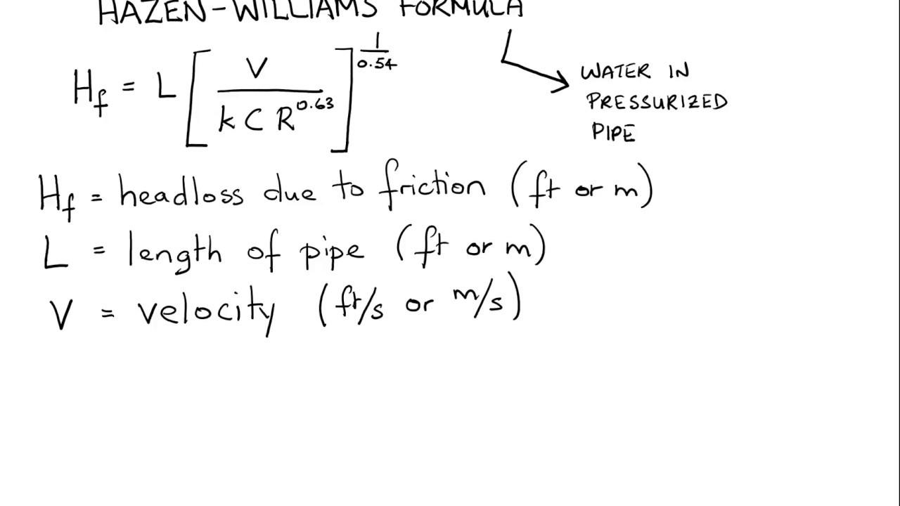
The friction loss through pipes can be calculated using various equations and models, such as the Darcy-Weisbach equation and the Hazen-Williams equation. These equations take into account the pipe's diameter, length, and roughness, as well as the fluid's velocity and viscosity. The calculations can be complex and require a good understanding of the underlying physics and mathematics. The results of the calculations can be used to predict the friction loss and optimize the design of piping systems.
Effects of Friction Loss
The friction loss through pipes can have significant effects on the performance of piping systems, including:
- A decrease in the fluid's pressure, which can reduce the system's overall efficiency
- A decrease in the fluid's flow rate, which can impact the system's ability to deliver the required amount of fluid
- An increase in the energy required to pump the fluid, which can increase the system's operating costs
Understanding the effects of friction loss is important for designing and operating efficient and effective piping systems.
Minimizing Friction Loss
There are several strategies that can be used to minimize the friction loss through pipes, including:
- Using smooth pipes to reduce the roughness and turbulence
- Optimizing the pipe's diameter and length to reduce the friction loss
- Using high-efficiency pumps and motors to reduce the energy required to pump the fluid
By understanding the causes and effects of friction loss, and using these strategies, it is possible to design and operate piping systems that are more efficient and effective, and that minimize the friction loss and its impact on the system's performance.
How to calculate friction loss in pumps?
To calculate friction loss in pumps, it is essential to understand the factors that contribute to this loss. Friction loss occurs when the fluid being pumped encounters resistance due to the pump's internal components, such as the impeller, pipes, and fittings. This resistance leads to a decrease in the pump's overall efficiency and can result in increased energy costs.
Understanding Friction Loss Components
To calculate friction loss, it is crucial to consider the various components that contribute to this loss. The main components include the pump's internal components, such as the impeller, volutes, and shafts, as well as the pipes and fittings used in the pumping system. The friction loss can be calculated using the following formula: hf = (f L v^2) / (2 g D), where hf is the head loss, f is the friction factor, L is the length of the pipe, v is the velocity of the fluid, g is the acceleration due to gravity, and D is the diameter of the pipe.
- The pump's internal components, such as the impeller and volutes, contribute to friction loss due to the resistance they create as the fluid flows through them.
- The pipes and fittings used in the pumping system also contribute to friction loss due to the resistance they create as the fluid flows through them.
- The friction factor, f, is a dimensionless quantity that depends on the Reynolds number and the roughness of the pipe.
Calculating Friction Loss in Pipes
To calculate friction loss in pipes, it is essential to consider the pipe's diameter, length, and roughness, as well as the fluid's velocity and viscosity. The Darcy-Weisbach equation can be used to calculate the head loss due to friction in pipes: hf = (f L v^2) / (2 g D).
- The pipe's diameter and length are critical factors in determining the friction loss.
- The fluid's velocity and viscosity also play a significant role in determining the friction loss.
- The Darcy-Weisbach equation is a widely used equation for calculating head loss due to friction in pipes.
Calculating Friction Loss in Fittings
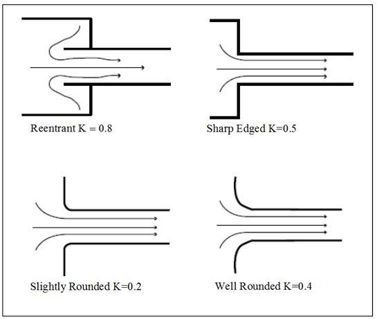
To calculate friction loss in fittings, such as elbows, tees, and valves, it is essential to consider the fitting's equivalent length and the fluid's velocity. The equivalent length of a fitting is the length of pipe that would produce the same head loss as the fitting.
- The fitting's equivalent length is a critical factor in determining the friction loss.
- The fluid's velocity also plays a significant role in determining the friction loss.
- The equivalent length of a fitting can be found using tables or charts that provide the equivalent length for different types of fittings.
Using Friction Loss Tables and Charts
Friction loss tables and charts are useful tools for calculating friction loss in pumps and piping systems. These tables and charts provide the friction factor, f, and the equivalent length for different types of fittings.
- Friction loss tables and charts provide a quick and easy way to calculate friction loss.
- These tables and charts are based on experimental data and theoretical calculations.
- The friction factor, f, and the equivalent length can be found using these tables and charts.
Minimizing Friction Loss in Pumps and Piping Systems
To minimize friction loss in pumps and piping systems, it is essential to use smooth pipes, large diameter pipes, and low-velocity fluids. Additionally, using pump's with high efficiency and low-friction impellers can also help minimize friction loss.
- Using smooth pipes can help reduce friction loss.
- Using large diameter pipes can also help reduce friction loss.
- Using low-velocity fluids can help minimize friction loss.
What is the unit of friction loss?

The unit of friction loss is typically measured in units of pressure or head loss. In the context of fluid flow, friction loss refers to the loss of energy due to the viscosity of the fluid and the roughness of the pipe or conduit. This loss of energy results in a decrease in the pressure or head of the fluid as it flows through the pipe.
Understanding the Concept of Friction Loss
Friction loss is an important concept in the field of fluid mechanics, as it can significantly impact the performance of pipelines and fluid systems. The unit of friction loss can vary depending on the specific context and the system being analyzed. For example, in some cases, friction loss may be measured in units of pounds per square inch (PSI) or feet of head. Some key points to consider when understanding friction loss include:
- The viscosity of the fluid plays a significant role in determining the amount of friction loss that occurs.
- The roughness of the pipe or conduit can also impact the amount of friction loss that occurs.
- Friction loss can result in a significant decrease in the pressure or head of the fluid as it flows through the pipe.
Factors that Affect Friction Loss
Several factors can affect the amount of friction loss that occurs in a fluid system. These factors include the velocity of the fluid, the viscosity of the fluid, and the roughness of the pipe or conduit. Additionally, the length and diameter of the pipe can also impact the amount of friction loss that occurs. Some key factors that can affect friction loss include:
- The velocity of the fluid, as higher velocities can result in greater friction loss.
- The viscosity of the fluid, as more viscous fluids can result in greater friction loss.
- The roughness of the pipe or conduit, as rougher surfaces can result in greater friction loss.
Calculating Friction Loss
Calculating friction loss is an important step in designing and optimizing fluid systems. The calculation of friction loss typically involves using the Darcy-Weisbach equation, which takes into account the velocity of the fluid, the viscosity of the fluid, and the roughness of the pipe or conduit. Some key points to consider when calculating friction loss include:
- The Darcy-Weisbach equation is a widely used method for calculating friction loss.
- The velocity of the fluid is a critical input parameter in the calculation of friction loss.
- The viscosity of the fluid is also an important input parameter in the calculation of friction loss.
Measuring Friction Loss
Measuring friction loss is an important step in validating the performance of fluid systems. The measurement of friction loss typically involves using pressure sensors or flow meters to measure the pressure or flow rate of the fluid at different points in the system. Some key points to consider when measuring friction loss include:
- Pressure sensors can be used to measure the pressure of the fluid at different points in the system.
- Flow meters can be used to measure the flow rate of the fluid at different points in the system.
- The accuracy of the measurement devices is critical in obtaining reliable measurements of friction loss.
Minimizing Friction Loss
Minimizing friction loss is an important goal in the design and optimization of fluid systems. The minimization of friction loss can result in significant energy savings and improved system performance. Some key strategies for minimizing friction loss include:
- Using smooth pipes or conduits to reduce the roughness of the surface.
- Optimizing the velocity of the fluid to minimize turbulence and friction loss.
- Using viscosity-reducing additives to reduce the viscosity of the fluid and minimize friction loss.
Frequently Asked Questions (FAQs)
What is Head Loss at Pipe Entrance and How is it Calculated?
Head loss at pipe entrance refers to the loss of energy or pressure that occurs when fluid flows from a large tank or reservoir into a pipe. This loss of energy is caused by the turbulence and friction that occurs as the fluid flows through the entrance of the pipe. The calculation of head loss at pipe entrance is an important aspect of fluid mechanics and hydraulics, as it helps engineers design and optimize pipe systems for various applications. The head loss at pipe entrance can be calculated using various equations and formulas, such as the Bernoulli's equation and the Darcy-Weisbach equation. These equations take into account the velocity of the fluid, the diameter of the pipe, and the roughness of the pipe surface.
What are the Different Types of Head Loss at Pipe Entrance Equations?
There are several types of head loss at pipe entrance equations, each with its own assumptions and limitations. The Borda-Carnot equation is a simple and widely used equation that calculates the head loss at pipe entrance based on the velocity of the fluid and the diameter of the pipe. The Hunt equation is another popular equation that takes into account the turbulence and friction that occurs at the entrance of the pipe. The Idelchik equation is a more complex equation that considers the roughness of the pipe surface and the Reynolds number of the flow. Each of these equations has its own advantages and disadvantages, and the choice of equation depends on the specific application and conditions of the pipe system.
How Does the Reynolds Number Affect Head Loss at Pipe Entrance?
The Reynolds number is a dimensionless quantity that characterizes the nature of fluid flow, and it plays a crucial role in determining the head loss at pipe entrance. The Reynolds number is defined as the ratio of inertial forces to viscous forces in the fluid, and it determines whether the flow is laminar or turbulent. A low Reynolds number indicates laminar flow, which is characterized by smooth and continuous flow with minimal turbulence. A high Reynolds number indicates turbulent flow, which is characterized by chaotic and irregular flow with significant turbulence. The head loss at pipe entrance is generally higher for turbulent flow than for laminar flow, and the Reynolds number is used to predict and calculate the head loss for different flow regimes.
What are the Practical Applications of Head Loss at Pipe Entrance Calculations?
The calculation of head loss at pipe entrance has numerous practical applications in various fields, including civil engineering, chemical engineering, and mechanical engineering. In water supply systems, head loss calculations are used to design and optimize pipelines and pumping stations to ensure efficient and reliable water distribution. In oil and gas industry, head loss calculations are used to design and optimize pipelines and pumping systems for the transportation of hydrocarbons. In power generation, head loss calculations are used to design and optimize cooling systems and pumping systems for power plants. The accurate calculation of head loss at pipe entrance is essential to ensure the efficient and reliable operation of these systems, and to minimize energy losses and costs.
Deja una respuesta
Entradas Relacionadas