
Flow of Air in Pipes Equation and Calculator
The flow of air in pipes is a fundamental concept in various engineering fields, including HVAC, aerospace, and chemical engineering. Calculating the flow rate, pressure drop, and velocity of air in pipes is crucial for designing and optimizing systems. The flow of air in pipes equation, also known as the Darcy-Weisbach equation, is a widely used formula to calculate the pressure drop in pipes. This article provides an overview of the equation and offers a calculator to simplify the calculation process, making it easier to determine the flow characteristics of air in pipes. Accurate calculations are essential.
- Understanding the Flow of Air in Pipes Equation and Calculator
- What is the formula for air flow in a pipe?
- What is the formula for flow through a pipe?
- How do you calculate the flow of air?
- What is the formula for air pressure in a pipe?
-
Frequently Asked Questions (FAQs)
- What is the Flow of Air in Pipes Equation and Calculator?
- How does the Flow of Air in Pipes Equation account for frictional losses?
- What are the key assumptions and limitations of the Flow of Air in Pipes Equation?
- How can the Flow of Air in Pipes Equation and Calculator be applied in real-world engineering applications?
Understanding the Flow of Air in Pipes Equation and Calculator
The flow of air in pipes is a critical aspect of various engineering applications, including HVAC (Heating, Ventilation, and Air Conditioning) systems, pneumatic systems, and compressed air systems. The flow of air in pipes can be calculated using the Darcy-Weisbach equation, which takes into account the friction factor, pipe diameter, pipe length, air density, and flow velocity. The calculator for the flow of air in pipes is a useful tool for engineers to determine the pressure drop and flow rate of air in pipes.
Introduction to the Darcy-Weisbach Equation
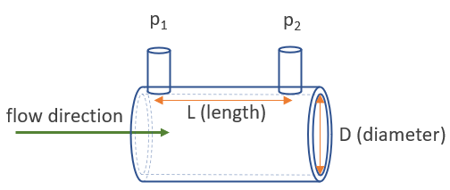
The Darcy-Weisbach equation is a widely used equation for calculating the head loss in pipes due to friction. The equation is given by: h_f = f (L/D) (V^2 / (2 g)), where h_f is the head loss, f is the friction factor, L is the pipe length, D is the pipe diameter, V is the flow velocity, and g is the acceleration due to gravity. The friction factor f depends on the Reynolds number, which is a dimensionless quantity that characterizes the nature of the flow.
Calculating the Friction Factor
The friction factor f can be calculated using the Colebrook-White equation, which is given by: 1 / sqrt(f) = -2 log10 ((epsilon / (3.7 D)) + (2.51 / (Re sqrt(f)))), where epsilon is the roughness height of the pipe, and Re is the Reynolds number. The Reynolds number Re is calculated using the equation: Re = (rho V D) / mu, where rho is the air density, V is the flow velocity, D is the pipe diameter, and mu is the dynamic viscosity of air.
Using the Flow of Air in Pipes Calculator
The flow of air in pipes calculator is a useful tool for engineers to determine the pressure drop and flow rate of air in pipes. The calculator takes into account the pipe diameter, pipe length, air density, flow velocity, and friction factor to calculate the head loss and pressure drop. The calculator can also be used to determine the required pipe size for a given flow rate and pressure drop.
Applications of the Flow of Air in Pipes Equation
The flow of air in pipes equation has various applications in HVAC systems, pneumatic systems, and compressed air systems. The equation can be used to design and optimize air distribution systems, pneumatic conveying systems, and compressed air systems. The equation can also be used to determine the energy losses in air distribution systems and to optimize the system performance.
Limitations and Assumptions of the Flow of Air in Pipes Equation
The flow of air in pipes equation has several limitations and assumptions. The equation assumes that the flow is steady-state and incompressible, and that the pipe is horizontal. The equation also assumes that the friction factor is constant and that the air density is uniform. The equation does not take into account the effects of turbulence and pipe roughness on the flow.
| Parameter | Unit | Description |
|---|---|---|
| Pipe Diameter | m | The diameter of the pipe |
| Pipe Length | m | The length of the pipe |
| Air Density | kg/m^3 | The density of air |
| Flow Velocity | m/s | The velocity of the air flow |
| Friction Factor | - | The factor that characterizes the frictional losses in the pipe |
What is the formula for air flow in a pipe?
The formula for air flow in a pipe is given by the Darcy-Weisbach equation, which is a widely used equation in fluid dynamics. The equation is as follows: Q = A √(2 ΔP / (ρ f L / D)), where Q is the volumetric flow rate, A is the cross-sectional area of the pipe, ΔP is the pressure drop across the pipe, ρ is the density of the fluid, f is the friction factor, L is the length of the pipe, and D is the diameter of the pipe.
Understanding the Darcy-Weisbach Equation
The Darcy-Weisbach equation is a dimensionless equation that can be used to calculate the flow rate of a fluid in a pipe. The equation takes into account the pressure drop, friction factor, and geometry of the pipe. To use the equation, you need to know the density and viscosity of the fluid, as well as the length and diameter of the pipe. Some key factors to consider when using the equation are:
- The friction factor can be calculated using the Colebrook-White equation or the Moody chart.
- The pressure drop can be calculated using the Bernoulli's equation or the energy equation.
- The density and viscosity of the fluid can be found in tables or charts.
Factors Affecting Air Flow in a Pipe
There are several factors that can affect the air flow in a pipe, including the pipe size, pipe material, and fluid properties. The pipe size can affect the flow rate and pressure drop, while the pipe material can affect the friction factor. The fluid properties, such as density and viscosity, can also affect the flow rate and pressure drop. Some key factors to consider are:
- The pipe size and pipe material can affect the flow rate and pressure drop.
- The fluid properties, such as density and viscosity, can affect the flow rate and pressure drop.
- The temperature and humidity of the fluid can also affect the flow rate and pressure drop.
Applications of the Darcy-Weisbach Equation
The Darcy-Weisbach equation has a wide range of applications in engineering and science, including pipe flow, channel flow, and fluid mechanics. The equation can be used to design and optimize pipelines, pumps, and turbines, as well as to predict the flow rate and pressure drop in a pipe. Some key applications are:
- Pipe flow: The equation can be used to calculate the flow rate and pressure drop in a pipe.
- Channel flow: The equation can be used to calculate the flow rate and water level in a channel.
- Fluid mechanics: The equation can be used to study the behavior of fluids in different flow regimes.
Limitations of the Darcy-Weisbach Equation
The Darcy-Weisbach equation has some limitations, including the assumption of laminar flow and the neglect of entrance effects. The equation is also sensitive to the value of the friction factor, which can be difficult to predict. Some key limitations are:
- The equation assumes laminar flow, which may not always be the case.
- The equation neglects entrance effects, which can be important in some cases.
- The equation is sensitive to the value of the friction factor, which can be difficult to predict.
Alternative Equations for Air Flow in a Pipe
There are several alternative equations that can be used to calculate the air flow in a pipe, including the Hazen-Williams equation and the Manning equation. These equations are simpler and easier to use than the Darcy-Weisbach equation, but they are also less accurate. Some key alternative equations are:
- The Hazen-Williams equation: This equation is a simplified version of the Darcy-Weisbach equation.
- The Manning equation: This equation is a empirical equation that can be used to calculate the flow rate in a pipe.
- The Chezy equation: This equation is a simple equation that can be used to calculate the flow rate in a pipe.
What is the formula for flow through a pipe?
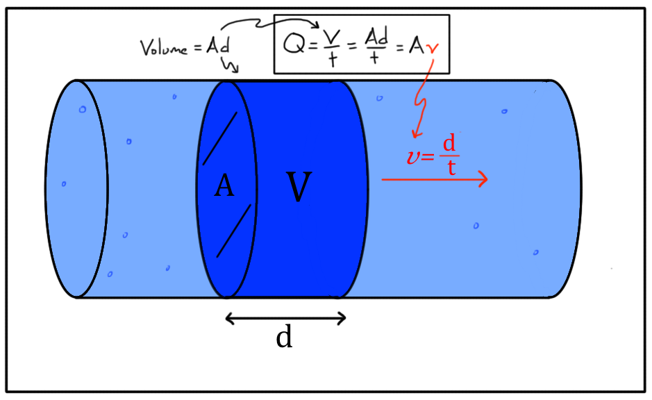
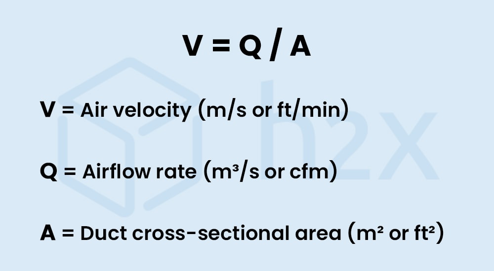
The formula for flow through a pipe is given by the equation Q = A v, where Q is the volumetric flow rate, A is the cross-sectional area of the pipe, and v is the velocity of the fluid. This equation is a fundamental concept in fluid mechanics and is used to calculate the rate at which a fluid flows through a pipe.
Understanding the Variables
To apply the formula for flow through a pipe, it is essential to understand the variables involved. The volumetric flow rate (Q) is the volume of fluid that flows through a given area per unit time. The cross-sectional area (A) of the pipe is the area of the pipe's interior, and the velocity (v) of the fluid is its speed. The formula can be used to calculate any of these variables if the other two are known.
- The volumetric flow rate can be calculated by multiplying the cross-sectional area by the velocity.
- The cross-sectional area can be calculated by dividing the volumetric flow rate by the velocity.
- The velocity can be calculated by dividing the volumetric flow rate by the cross-sectional area.
Important Factors Affecting Flow
Several factors can affect the flow of a fluid through a pipe, including the pipe's diameter, the fluid's viscosity, and the pressure difference between the two ends of the pipe. The pipe's diameter affects the cross-sectional area, which in turn affects the volumetric flow rate. The fluid's viscosity affects the velocity of the fluid, as more viscous fluids flow more slowly. The pressure difference between the two ends of the pipe also affects the velocity of the fluid, as a greater pressure difference results in a faster velocity.
- A larger pipe's diameter results in a larger cross-sectional area and a greater volumetric flow rate.
- A more viscous fluid results in a slower velocity and a lower volumetric flow rate.
- A greater pressure difference results in a faster velocity and a greater volumetric flow rate.
Types of Flow
There are several types of flow that can occur in a pipe, including laminar flow and turbulent flow. Laminar flow occurs when the fluid flows in parallel layers, with no mixing between the layers. Turbulent flow occurs when the fluid flows in a chaotic, mixed manner. The type of flow that occurs depends on the velocity of the fluid and the pipe's diameter.
- Laminar flow occurs at low velocities and in small pipes.
- Turbulent flow occurs at high velocities and in large pipes.
- The Reynolds number can be used to predict whether laminar or turbulent flow will occur.
Applications of the Formula
The formula for flow through a pipe has many practical applications in fields such as engineering, physics, and chemistry. It can be used to design pipelines, pumps, and other fluid-handling systems. It can also be used to calculate the flow rate of a fluid in a pipe and to predict the pressure drop that will occur as the fluid flows through the pipe.
- The formula can be used to design pipelines to transport oil, gas, and other fluids.
- The formula can be used to calculate the flow rate of a fluid in a pipe and to predict the pressure drop that will occur.
- The formula is essential for engineering and physics applications, such as fluid mechanics and thermodynamics.
Limitations of the Formula
The formula for flow through a pipe has several limitations and assumptions. It assumes that the fluid is incompressible, that the flow is steady, and that the pipe is circular. It also assumes that the fluid's viscosity is constant and that the pipe's surface is smooth. In reality, these assumptions may not always be valid, and the formula may need to be modified or corrected to account for real-world conditions.
- The formula assumes that the fluid is incompressible, which may not be true for gases or other compressible fluids.
- The formula assumes that the flow is steady, which may not be true for unsteady or transient flows.
- The formula assumes that the pipe is circular, which may not be true for non-circular pipes or channels.
How do you calculate the flow of air?
To calculate the flow of air, you need to understand the principles of fluid dynamics and the equations of motion that govern the behavior of fluids, including air. The flow of air can be calculated using various methods, including the continuity equation, which states that the mass flow rate of air is constant throughout a system. Additionally, the Bernoulli's equation can be used to calculate the flow of air by relating the pressure, velocity, and elevation of the air.
Understanding Air Flow Parameters
To calculate the flow of air, you need to understand the parameters that affect air flow, including temperature, humidity, pressure, and velocity. These parameters can be measured using various instruments, such as anemometers, thermometers, and barometers. The following are some of the key parameters to consider:
- Temperature: affects the density of air and its viscosity
- Humidity: affects the density of air and its thermal conductivity
- Pressure: affects the flow rate of air and its velocity
Using the Continuity Equation
The continuity equation is a fundamental concept in fluid dynamics that states that the mass flow rate of air is constant throughout a system. The equation can be expressed as: ρ1A1V1 = ρ2A2V2, where ρ is the density of air, A is the cross-sectional area, and V is the velocity of air. The following are some of the key steps to use the continuity equation:
- Measure the velocity of air at two points in the system
- Measure the cross-sectional area of the system at two points
- Calculate the density of air at two points using the ideal gas law
Applying Bernoulli's Equation
Bernoulli's equation is a fundamental concept in fluid dynamics that relates the pressure, velocity, and elevation of air. The equation can be expressed as: P1/ρ + 1/2V1^2 + gz1 = P2/ρ + 1/2V2^2 + gz2, where P is the pressure, V is the velocity, g is the acceleration due to gravity, and z is the elevation. The following are some of the key steps to apply Bernoulli's equation:
- Measure the pressure of air at two points in the system
- Measure the velocity of air at two points in the system
- Calculate the elevation of air at two points in the system
Considering Frictional Losses
Frictional losses can occur in air flow systems due to the viscosity of air and the roughness of the system. These losses can be calculated using the Darcy-Weisbach equation, which relates the pressure drop to the friction factor, length, and velocity of air. The following are some of the key steps to consider frictional losses:
- Measure the friction factor of the system using experiments or empirical correlations
- Calculate the pressure drop using the Darcy-Weisbach equation
- Consider the effects of frictional losses on the overall air flow and system performance
Using Computational Fluid Dynamics
Computational fluid dynamics (CFD) is a powerful tool for simulating and analyzing air flow systems. CFD can be used to model complex geometries, simulate turbulence, and predict air flow patterns. The following are some of the key steps to use CFD:
- Create a 3D model of the air flow system using computer-aided design (CAD) software
- Define the boundary conditions and initial conditions of the system
- Run the simulation using CFD software and analyze the results
What is the formula for air pressure in a pipe?
The formula for air pressure in a pipe is given by the equation P = ρgh + P0, where P is the absolute pressure at a point in the pipe, ρ is the density of the fluid (air), g is the acceleration due to gravity, h is the height of the fluid column above the point, and P0 is the atmospheric pressure.
Air Pressure Calculation
The calculation of air pressure in a pipe is crucial in understanding the behavior of fluids in pneumatic systems. To calculate the air pressure, one needs to consider the density of the air, the height of the air column, and the atmospheric pressure. The formula can be broken down into the following steps:
- Determine the density of the air, which can be calculated using the ideal gas law.
- Calculate the height of the air column above the point where the pressure is being measured.
- Determine the atmospheric pressure, which is the pressure exerted by the atmosphere at a given location.
Factors Affecting Air Pressure
Several factors can affect the air pressure in a pipe, including temperature, humidity, and flow rate. Changes in these factors can result in changes to the air pressure, which can impact the performance of pneumatic systems. For example, an increase in temperature can lead to an increase in air pressure, while an increase in humidity can lead to a decrease in air pressure. The following are some of the key factors that can affect air pressure:
- Temperature: An increase in temperature can lead to an increase in air pressure.
- Humidity: An increase in humidity can lead to a decrease in air pressure.
- Flow rate: An increase in flow rate can lead to a decrease in air pressure.
Applications of Air Pressure Formula
The air pressure formula has numerous applications in various fields, including engineering, physics, and chemistry. It is used to design and optimize pneumatic systems, such as air compressors and pneumatic cylinders. The formula is also used to calculate the pressure drop in pipes and tubes, which is essential in designing fluid power systems. Some of the key applications of the air pressure formula include:
- Pneumatic system design: The formula is used to design and optimize pneumatic systems.
- Fluid power systems: The formula is used to calculate the pressure drop in pipes and tubes.
- Air compressor design: The formula is used to design and optimize air compressors.
Limitations of Air Pressure Formula
The air pressure formula has several limitations, including the assumption of ideal gas behavior and the neglect of frictional losses. The formula also assumes that the air is incompressible, which is not always the case. In addition, the formula does not account for turbulent flow, which can occur in pipes and tubes. Some of the key limitations of the air pressure formula include:
- Ideal gas assumption: The formula assumes that the air behaves as an ideal gas.
- Neglect of frictional losses: The formula neglects the frictional losses that occur in pipes and tubes.
- Incompressibility assumption: The formula assumes that the air is incompressible.
Derivation of Air Pressure Formula
The air pressure formula can be derived from the principles of fluid mechanics and the ideal gas law. The derivation involves the use of differential equations and integration to obtain the final formula. The formula can be derived by considering the force balance on a fluid element and the equation of state for an ideal gas. Some of the key steps in deriving the air pressure formula include:
- Force balance: The force balance on a fluid element is used to derive the equation for the pressure gradient.
- Equation of state: The equation of state for an ideal gas is used to relate the pressure and density of the air.
- Integration: The equation for the pressure gradient is integrated to obtain the final formula for the air pressure.
Frequently Asked Questions (FAQs)
What is the Flow of Air in Pipes Equation and Calculator?
The Flow of Air in Pipes Equation is a mathematical formula used to calculate the velocity and flow rate of air moving through a pipe. This equation takes into account various factors such as the diameter of the pipe, the pressure drop along the pipe, and the viscosity of the air. The equation is commonly used in engineering applications, particularly in the design and optimization of pneumatic systems, air conditioning systems, and ventilation systems. The Calculator is a tool that simplifies the process of solving the equation by providing a user-friendly interface to input the necessary parameters and obtain the desired results. By using the Flow of Air in Pipes Equation and Calculator, engineers and designers can easily determine the flow characteristics of air in pipes and make informed decisions to ensure the efficient and safe operation of their systems.
How does the Flow of Air in Pipes Equation account for frictional losses?
The Flow of Air in Pipes Equation accounts for frictional losses by incorporating the Darcy-Weisbach equation, which relates the pressure drop along the pipe to the friction factor, length of the pipe, and the velocity of the air. The friction factor is a dimensionless quantity that depends on the Reynolds number, which characterizes the nature of the fluid flow. The equation also considers the roughness of the pipe, which affects the frictional losses. By including these factors, the Flow of Air in Pipes Equation provides a more accurate prediction of the flow rate and velocity of air in pipes, taking into account the energy losses due to friction. This is particularly important in long pipelines or complex pipe networks, where frictional losses can significantly impact the overall performance of the system. The Calculator also allows users to input the roughness and length of the pipe, making it easier to account for frictional losses in their calculations.
What are the key assumptions and limitations of the Flow of Air in Pipes Equation?
The Flow of Air in Pipes Equation is based on several key assumptions and limitations. One of the main assumptions is that the flow is steady-state, meaning that the flow rate and velocity do not change over time. Additionally, the equation assumes that the air is incompressible, which is a reasonable assumption for most engineering applications. However, for high-speed flows or high-altitude applications, the compressibility of air must be considered. Another limitation is that the equation is only applicable for circular pipes, and modifications are required for non-circular or irregularly shaped pipes. The Calculator also assumes that the user has a good understanding of the input parameters and their units, as incorrect input can lead to inaccurate results. Furthermore, the equation does not account for heat transfer or mass transfer effects, which can be significant in certain applications. By understanding these assumptions and limitations, users can apply the Flow of Air in Pipes Equation and Calculator with confidence and accuracy.
How can the Flow of Air in Pipes Equation and Calculator be applied in real-world engineering applications?
The Flow of Air in Pipes Equation and Calculator can be applied in a wide range of real-world engineering applications, including the design and optimization of pneumatic systems, air conditioning systems, and ventilation systems. For example, in building design, the equation can be used to determine the required pipe size and fan capacity to ensure adequate ventilation and comfortable indoor air quality. In industrial processes, the equation can be used to optimize the pneumatic conveying of materials, such as powders or granules, to minimize energy consumption and maintenance costs. The Calculator can also be used to troubleshoot existing systems, identifying bottlenecks and inefficiencies in the pipe network. By applying the Flow of Air in Pipes Equation and Calculator, engineers and designers can create more efficient, safe, and reliable systems, which can lead to cost savings, increased productivity, and improved environmental sustainability. Additionally, the equation and calculator can be used in research and development to study the fundamentals of fluid flow and heat transfer, leading to new innovations and technological advancements.
Deja una respuesta
Entradas Relacionadas