
Power Screw Moment and Axial Load Formulas and Calculator
The power screw moment and axial load are critical parameters in screw design, determining the screw's efficiency and reliability. Calculating these values accurately is essential to ensure the screw's proper functioning and prevent damage or failure. This article provides a comprehensive overview of the power screw moment and axial load formulas, along with a calculator to simplify the calculation process. Understanding these formulas and using the calculator can help engineers and designers optimize their screw designs, reducing errors and improving overall performance. The formulas and calculator are essential tools for efficient screw design and analysis.
- Power Screw Moment and Axial Load Formulas and Calculator
- How to calculate axial load on a screw?
- What is the formula for a power screw?
- What is the formula for the axial force of a screw?
- What is the formula for a screw?
-
Frequently Asked Questions (FAQs)
- What is the Power Screw Moment and Axial Load Formulas and Calculator?
- How do I use the Power Screw Moment and Axial Load Formulas and Calculator?
- What are the key factors that affect the Power Screw Moment and Axial Load Formulas and Calculator?
- What are the limitations and assumptions of the Power Screw Moment and Axial Load Formulas and Calculator?
Power Screw Moment and Axial Load Formulas and Calculator
The power screw is a mechanical device used to convert rotational motion into linear motion, and it is commonly used in various applications such as jacks, presses, and lifting devices. The moment and axial load are two important parameters that need to be considered when designing a power screw. The moment is the rotational force that is applied to the screw, while the axial load is the force that is applied along the axis of the screw.
Introduction to Power Screw Moment and Axial Load Formulas
The power screw moment and axial load formulas are used to calculate the required torque and force to achieve a specific linear motion. The formulas take into account the lead angle, coefficient of friction, and thread diameter of the screw. The lead angle is the angle between the thread and the axis of the screw, while the coefficient of friction is the ratio of the frictional force to the normal force.
Power Screw Moment Formula
The power screw moment formula is given by: M = (F d) / (2 tan(φ) cos(λ)), where M is the moment, F is the axial load, d is the thread diameter, φ is the coefficient of friction, and λ is the lead angle. This formula is used to calculate the required moment to achieve a specific axial load.
Axial Load Formula
The axial load formula is given by: F = (M 2 tan(φ) cos(λ)) / d, where F is the axial load, M is the moment, d is the thread diameter, φ is the coefficient of friction, and λ is the lead angle. This formula is used to calculate the required axial load to achieve a specific moment.
Power Screw Calculator
A power screw calculator is a tool used to calculate the required torque and force to achieve a specific linear motion. The calculator takes into account the lead angle, coefficient of friction, and thread diameter of the screw, and provides the required moment and axial load.
Applications of Power Screw Moment and Axial Load Formulas
The power screw moment and axial load formulas have various applications in mechanical engineering, design, and manufacturing. They are used to design and optimize power screws for specific applications, and to ensure that the screw can withstand the required loads and moments.
| Parameter | Unit | Description |
|---|---|---|
| Moment | Nm | The rotational force applied to the screw |
| Axial Load | N | The force applied along the axis of the screw |
| Lead Angle | degrees | The angle between the thread and the axis of the screw |
| Coefficient of Friction | The ratio of the frictional force to the normal force | |
| Thread Diameter | mm | The diameter of the thread |
How to calculate axial load on a screw?
To calculate the axial load on a screw, you need to understand the mechanics of the screw and the forces acting on it. The axial load is the force that acts along the centerline of the screw, either in compression or tension. This load can be caused by various factors such as weight, pressure, or torque. The calculation of axial load involves determining the magnitude and direction of the force acting on the screw.
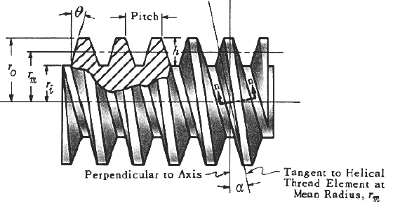
Understanding Screw Geometry
To calculate the axial load on a screw, you need to understand the geometry of the screw, including its diameter, pitch, and thread length. The geometry of the screw affects the surface area in contact with the surrounding material, which in turn affects the frictional forces acting on the screw. The axial load calculation involves using formulas that take into account the screw's geometry, such as:
- Screw diameter: The diameter of the screw affects the surface area in contact with the surrounding material.
- Pitch: The pitch of the screw affects the rate at which the screw advances when turned.
- Thread length: The thread length of the screw affects the amount of material in contact with the screw.
Material Properties
The material properties of the screw and the surrounding material also play a crucial role in calculating the axial load. The strength and stiffness of the materials affect the deformation and stress on the screw. The calculation of axial load involves using material constants such as Young's modulus and Poisson's ratio. The material properties can be:
- Elastic modulus: A measure of the material's stiffness.
- Poisson's ratio: A measure of the material's lateral strain response to axial loading.
- Yield strength: The maximum stress that a material can withstand without deforming plastically.
Load Calculation Methods
There are several methods for calculating the axial load on a screw, including analytical and numerical methods. The analytical methods involve using formulas and equations to calculate the load, while the numerical methods involve using computer simulations and finite element analysis. The load calculation methods can be:
- Simple axial load: A calculation that assumes a constant axial load along the length of the screw.
- Bending load: A calculation that takes into account the bending moment acting on the screw.
- Torsional load: A calculation that takes into account the torque acting on the screw.
Factors Affecting Axial Load
Several factors can affect the axial load on a screw, including temperature, humidity, and vibration. The temperature and humidity can affect the material properties of the screw and the surrounding material, while the vibration can cause dynamic loading on the screw. The factors affecting axial load can be:
- Temperature effects: Changes in temperature can cause thermal expansion and contraction of the materials.
- Humidity effects: Changes in humidity can cause swelling or shrinking of the materials.
- Vibration effects: Vibration can cause dynamic loading and fatigue of the screw.
Applications and Considerations
The calculation of axial load on a screw has several applications and considerations, including design, safety, and maintenance. The axial load calculation can be used to optimize the design of the screw and the surrounding material, as well as to predict the failure of the screw. The applications and considerations can be:
- Design optimization: The axial load calculation can be used to optimize the design of the screw and the surrounding material.
- Safety factors: The axial load calculation can be used to determine the safety factors and failure probabilities of the screw.
- Maintenance schedules: The axial load calculation can be used to determine the maintenance schedules and inspection intervals for the screw.
What is the formula for a power screw?

The formula for a power screw is typically represented by the equation: τ = (F d) / (2 π), where τ is the torque required to turn the screw, F is the force applied to the screw, and d is the diameter of the screw. This formula is used to calculate the efficiency of a power screw and to determine the torque required to achieve a specific linear motion.
Understanding the Power Screw Formula
The power screw formula is based on the principle of leverage, which states that the mechanical advantage of a screw is proportional to the ratio of the diameter to the pitch. To calculate the torque required to turn a power screw, you need to know the force applied to the screw, the diameter of the screw, and the pitch of the screw. The formula can be used in a variety of applications, including:
- Calculating the torque required to turn a screw in a mechanical system
- Determining the efficiency of a power screw in a given application
- Designing a power screw to achieve a specific linear motion
Key Components of the Power Screw Formula
The power screw formula involves several key components, including the force applied to the screw, the diameter of the screw, and the pitch of the screw. The force applied to the screw is typically measured in Newtons (N), while the diameter and pitch are typically measured in millimeters (mm) or inches (in). To ensure accurate calculations, it is essential to use the correct units and to consider the limitations of the formula, including:
- Frictional losses, which can reduce the efficiency of the power screw
- Material properties, which can affect the strength and durability of the screw
- Environmental factors, which can impact the performance of the power screw
Applications of the Power Screw Formula
The power screw formula has a wide range of applications in various fields, including mechanical engineering, aerospace engineering, and automotive engineering. The formula can be used to design and optimize power screws for use in linear motion systems, rotary motion systems, and other mechanical systems. Some examples of applications include:
- Linear actuators, which use power screws to achieve precise motion control
- Robotics, which use power screws to achieve flexible motion and high accuracy
- Machine tools, which use power screws to achieve high precision and repeatability
Limitations of the Power Screw Formula
The power screw formula has several limitations, including frictional losses, material properties, and environmental factors. To ensure accurate calculations, it is essential to consider these limitations and to use correction factors or empirical models to account for them. Some examples of limitations include:
- Frictional losses, which can reduce the efficiency of the power screw by up to 50%
- Material properties, which can affect the strength and durability of the screw, such as yield strength and ultimate strength
- Environmental factors, which can impact the performance of the power screw, such as temperature and humidity
Design Considerations for Power Screws
When designing a power screw, there are several key considerations to keep in mind, including the diameter, pitch, and material of the screw. The diameter of the screw should be chosen based on the required torque and linear motion, while the pitch should be chosen based on the required speed and accuracy. The material of the screw should be chosen based on the required strength, durability, and corrosion resistance, and some examples of design considerations include:
- Diameter, which affects the torque and linear motion of the screw
- Pitch, which affects the speed and accuracy of the screw
- Material, which affects the strength, durability, and corrosion resistance of the screw
What is the formula for the axial force of a screw?

The formula for the axial force of a screw is given by the equation F = (G d^4) / (8 L), where F is the axial force, G is the modulus of rigidity, d is the diameter of the screw, and L is the lead of the screw. This formula is used to calculate the force required to turn a screw and is an important consideration in the design of screw-based systems.
Understanding the Variables
The variables in the formula are crucial to understanding how the axial force of a screw is calculated. The modulus of rigidity (G) is a measure of the screw's resistance to deformation, while the diameter (d) affects the screw's strength and stability. The lead (L) of the screw, which is the distance the screw travels in one rotation, also plays a significant role in determining the axial force. The formula can be broken down into the following components:
- The modulus of rigidity (G) is typically a constant value for a given material.
- The diameter (d) of the screw is a critical factor in determining its strength and stability.
- The lead (L) of the screw affects its ability to convert rotational force into linear motion.
Calculating Axial Force
To calculate the axial force of a screw, the values of G, d, and L must be known. The formula F = (G d^4) / (8 L) can then be used to calculate the force required to turn the screw. It is essential to use the correct units for each variable to ensure an accurate calculation. The formula can be applied in various scenarios, including:
- Screw design: to determine the required diameter and lead for a screw to withstand a specific axial force.
- Material selection: to choose a material with the suitable modulus of rigidity for the application.
- System optimization: to optimize the performance of a screw-based system by adjusting the axial force and other parameters.
Factors Affecting Axial Force
Several factors can affect the axial force of a screw, including the coefficient of friction, the thread angle, and the screw material. These factors can impact the screw's performance and must be considered when designing or selecting a screw for a particular application. The effects of these factors can be summarized as follows:
- The coefficient of friction affects the force required to turn the screw and can be influenced by the screw's surface finish and the surrounding environment.
- The thread angle affects the screw's ability to convert rotational force into linear motion and can impact its efficiency.
- The screw material affects the screw's strength, stability, and resistance to deformation.
Applications of Axial Force Formula
The formula for the axial force of a screw has various applications in fields such as mechanical engineering, materials science, and manufacturing. It is used to design and optimize screw-based systems, including machinery, equipment, and fasteners. The formula can be applied in different contexts, including:
- Design and development: to create new screw-based systems or improve existing ones.
- Troubleshooting: to identify and resolve issues with screw-based systems.
- Maintenance and repair: to ensure the proper functioning and longevity of screw-based systems.
Limitations and Assumptions
The formula for the axial force of a screw is based on certain assumptions and has limitations. It assumes a static load and does not account for dynamic loads or cyclic loading. Additionally, the formula does not consider the effects of wear and tear or corrosion on the screw's performance. The limitations of the formula can be summarized as follows:
- The formula assumes a static load, which may not be representative of real-world applications.
- The formula does not account for dynamic loads or cyclic loading, which can affect the screw's performance and lifespan.
- The formula does not consider the effects of wear and tear or corrosion, which can impact the screw's strength and stability.
What is the formula for a screw?

The formula for a screw is a complex combination of various factors, including its pitch, diameter, and thread angle. The pitch of a screw refers to the distance between two consecutive threads, while the diameter is the measurement of the screw's cross-sectional area. The thread angle, on the other hand, is the angle at which the threads are cut into the material. These factors are crucial in determining the torque and strength of the screw.
Understanding Screw Threads
Screw threads are the helical grooves that are cut into the material, allowing the screw to grip and fasten objects together. The formula for a screw thread takes into account the major diameter, minor diameter, and pitch diameter. The major diameter is the largest diameter of the screw thread, while the minor diameter is the smallest. The pitch diameter is the average diameter of the screw thread. Some key factors to consider when understanding screw threads include:
- Thread pitch: The distance between two consecutive threads.
- Thread angle: The angle at which the threads are cut into the material.
- Thread depth: The distance from the crest of one thread to the root of the next.
Calculating Screw Torque
The torque of a screw is a critical factor in determining its strength and stability. The formula for calculating screw torque takes into account the force applied to the screw, as well as the distance from the axis of rotation to the point where the force is applied. The torque formula is given by: Torque = Force x Distance. Some key factors to consider when calculating screw torque include:
- Force: The amount of pressure or tension applied to the screw.
- Distance: The measurement from the axis of rotation to the point where the force is applied.
- Friction: The resistance to motion that occurs between the screw and the material it is fastening.
Designing Screw Fasteners
Screw fasteners are designed to provide a strong and reliable connection between two objects. The formula for designing screw fasteners takes into account the material properties, load requirements, and environmental conditions. Some key factors to consider when designing screw fasteners include:
- Material selection: Choosing the right material for the screw and the objects being fastened.
- Load calculation: Determining the weight or pressure that the screw will be required to withstand.
- Safety factors: Accounting for uncertainties and variations in the design and manufacturing process.
Understanding Screw Drive Systems
Screw drive systems are designed to transmit rotational motion from a motor or other power source to a screw or other linear motion device. The formula for understanding screw drive systems takes into account the screw pitch, motor speed, and load requirements. Some key factors to consider when understanding screw drive systems include:
- Screw pitch: The distance between two consecutive threads.
- Motor speed: The rotational speed of the motor or power source.
- Load requirements: The weight or pressure that the screw drive system will be required to withstand.
Optimizing Screw Performance
Optimizing screw performance is critical in ensuring the reliability and efficiency of a system or machine. The formula for optimizing screw performance takes into account the screw geometry, material properties, and operating conditions. Some key factors to consider when optimizing screw performance include:
- Screw geometry: The shape and size of the screw thread.
- Material properties: The strength, stiffness, and ductility of the screw material.
- Operating conditions: The temperature, humidity, and vibration levels that the screw will be exposed to.
Frequently Asked Questions (FAQs)
What is the Power Screw Moment and Axial Load Formulas and Calculator?
The Power Screw Moment and Axial Load Formulas and Calculator is a tool used to calculate the moment and axial load of a power screw. A power screw is a type of screw that is used to convert rotary motion into linear motion, and is commonly used in applications such as linear actuators, ball screws, and lead screws. The formulas used to calculate the moment and axial load of a power screw take into account the screw diameter, lead, coefficient of friction, and applied force. The calculator is a useful tool for engineers and designers who need to determine the performance and efficiency of a power screw in a given application.
How do I use the Power Screw Moment and Axial Load Formulas and Calculator?
To use the Power Screw Moment and Axial Load Formulas and Calculator, you will need to input the known values of the power screw, such as the screw diameter, lead, coefficient of friction, and applied force. The calculator will then use these values to calculate the moment and axial load of the power screw. The formulas used by the calculator are based on the mechanics of materials and the kinematics of motion, and take into account the frictional losses and efficiency of the power screw. By using the calculator, you can quickly and easily determine the performance and efficiency of a power screw, and make informed decisions about the design and operation of the screw.
What are the key factors that affect the Power Screw Moment and Axial Load Formulas and Calculator?
The key factors that affect the Power Screw Moment and Axial Load Formulas and Calculator are the screw diameter, lead, coefficient of friction, and applied force. The screw diameter and lead determine the pitch and thread angle of the screw, which in turn affect the frictional losses and efficiency of the screw. The coefficient of friction is a measure of the frictional forces that oppose the motion of the screw, and can have a significant impact on the performance and efficiency of the screw. The applied force is the external force that is applied to the screw, and can affect the moment and axial load of the screw. By understanding the effects of these key factors, you can use the calculator to optimize the design and operation of the power screw.
What are the limitations and assumptions of the Power Screw Moment and Axial Load Formulas and Calculator?
The Power Screw Moment and Axial Load Formulas and Calculator are based on a number of assumptions and limitations, including the simplification of the frictional forces and the neglect of dynamic effects. The calculator assumes that the frictional forces are constant and uniformly distributed along the length of the screw, and neglects the effects of vibration and resonance. The calculator also assumes that the screw material is homogeneous and isotropic, and that the applied force is constant and uniformly distributed. By understanding these limitations and assumptions, you can use the calculator with confidence and accuracy, and make informed decisions about the design and operation of the power screw. Engineers and designers should always verify the results of the calculator with experimental data and field testing to ensure the reliability and safety of the power screw.
Deja una respuesta
Entradas Relacionadas