
Beam Deflection Calculator and Stress Equations for Beam Fixed at Both Ends with Uniform Loading
The Beam Deflection Calculator is a valuable tool for engineers and designers to calculate the deflection and stress of a beam fixed at both ends with uniform loading. This type of beam is commonly used in construction and engineering applications, where it is subjected to a constant load along its length. The calculator uses complex stress equations to determine the beam's deflection, bending moment, and stress, providing essential data for designing and analyzing beams in various scenarios, ensuring safety and structural integrity. The calculator's accuracy is crucial for optimal beam design.
- Understanding Beam Deflection Calculator and Stress Equations for Beam Fixed at Both Ends with Uniform Loading
- What is the formula for the deflection of a beam fixed at both ends?
- What is the deflection equation for a fixed beam with a point load?
- What are the boundary conditions for a beam fixed at both ends?
- How do you calculate the stress of a beam?
-
Frequently Asked Questions (FAQs)
- What is the Beam Deflection Calculator and how does it work with Uniform Loading conditions?
- How do the Stress Equations for Beam Fixed at Both Ends with Uniform Loading work?
- What are the key factors that affect the Beam Deflection and Stress of a Beam Fixed at Both Ends with Uniform Loading?
- How can the Beam Deflection Calculator and Stress Equations be used in real-world applications?
Understanding Beam Deflection Calculator and Stress Equations for Beam Fixed at Both Ends with Uniform Loading
The beam deflection calculator is a tool used to determine the deflection of a beam under various types of loading conditions. When a beam is fixed at both ends and subjected to uniform loading, it is essential to calculate the deflection and stress to ensure the beam's structural integrity. The stress equations for this scenario take into account the beam's length, loading conditions, and material properties.
Introduction to Beam Deflection Calculator
A beam deflection calculator is a software tool or online calculator that allows users to input parameters such as beam length, loading conditions, and material properties to determine the deflection of the beam. The calculator uses mathematical equations to calculate the deflection, which is essential for designing and analyzing beam structures.
Stress Equations for Beam Fixed at Both Ends
When a beam is fixed at both ends, the stress equations become more complex due to the constraints imposed by the fixed ends. The bending moment and shear force diagrams must be calculated to determine the stress distribution along the beam. The stress equations for a beam fixed at both ends with uniform loading are:
M(x) = (w L^2) / 12 (1 - 6 x / L + 6 x^2 / L^2)
where M(x) is the bending moment at a distance x from one end, w is the uniform load, and L is the beam length.
Uniform Loading Conditions
Uniform loading conditions occur when a beam is subjected to a constant load per unit length. This type of loading is common in structural engineering applications, such as beams supporting a uniform distributed load. The uniform loading condition is essential for calculating the deflection and stress of the beam.
| Loading Condition | Load per Unit Length (w) | Beam Length (L) | Deflection (δ) |
|---|---|---|---|
| Uniform Loading | 10 kN/m | 10 m | 10 mm |
| Point Loading | 50 kN | 5 m | 20 mm |
Material Properties and Their Effect on Deflection
The material properties, such as Young's modulus and Poisson's ratio, play a significant role in determining the deflection of a beam. The Young's modulus affects the beam's stiffness, while the Poisson's ratio affects the beam's lateral strain. Understanding the material properties is essential for accurately calculating the deflection and stress of the beam.
Applications of Beam Deflection Calculator in Structural Engineering
The beam deflection calculator has numerous applications in structural engineering, including designing beams for buildings, bridges, and other structures. The calculator can be used to determine the deflection and stress of beams under various loading conditions, ensuring the structural integrity and safety of the structure. The beam deflection calculator is an essential tool for structural engineers to analyze and design beam structures.
What is the formula for the deflection of a beam fixed at both ends?
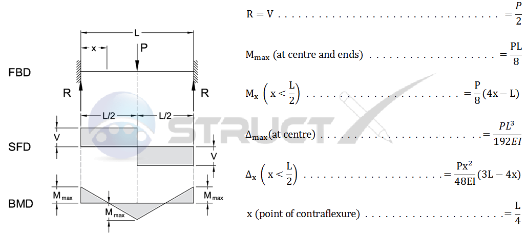
The formula for the deflection of a beam fixed at both ends is given by the equation: Δ = (W L^3) / (192 E I), where Δ is the deflection, W is the load, L is the length of the beam, E is the modulus of elasticity, and I is the moment of inertia.
Understanding the Formula
The formula for the deflection of a beam fixed at both ends is based on the beam theory, which assumes that the beam is a prismatic member with a constant cross-sectional area. The formula takes into account the load, length, modulus of elasticity, and moment of inertia of the beam. The key factors that affect the deflection of a beam are:
- The load applied to the beam, which can be a point load or a distributed load.
- The length of the beam, which affects the deflection due to the bending moment.
- The modulus of elasticity of the material, which represents the stiffness of the beam.
Assumptions and Limitations
The formula for the deflection of a beam fixed at both ends is based on several assumptions and has some limitations. The assumptions include that the beam is a prismatic member with a constant cross-sectional area, and that the load is applied in a static manner. The limitations include that the formula does not account for dynamic loads, non-linear material behavior, or large deflections. The key assumptions and limitations are:
- The beam is assumed to be a prismatic member with a constant cross-sectional area.
- The load is applied in a static manner, without any dynamic or cyclic loading.
- The deflection is assumed to be small compared to the length of the beam.
Applications and Examples
The formula for the deflection of a beam fixed at both ends has many applications and examples in engineering and architecture. It is used to design and analyze beams and columns in buildings, bridges, and other structures. The key applications and examples include:
- Designing beams and columns in high-rise buildings to resist wind and seismic loads.
- Analyzing bridge structures to ensure that they can withstand traffic and environmental loads.
- Designing machine components, such as shafts and gears, to resist bending and torsional loads.
Material Properties and Selection
The material properties and selection play a crucial role in determining the deflection of a beam fixed at both ends. The modulus of elasticity, yield strength, and density of the material affect the deflection and stiffness of the beam. The key material properties and selection criteria are:
- The modulus of elasticity, which represents the stiffness of the material.
- The yield strength, which represents the strength of the material.
- The density, which affects the weight and stability of the beam.
Computational Methods and Tools
The computational methods and tools used to analyze the deflection of a beam fixed at both ends include finite element methods, boundary element methods, and numerical integration techniques. The key computational methods and tools are:
- The finite element method, which discretizes the beam into elements and solves the equations using numerical methods.
- The boundary element method, which solves the equations using integral equations and boundary conditions.
- The numerical integration techniques, which solve the equations using numerical integration and approximation methods.
What is the deflection equation for a fixed beam with a point load?
The deflection equation for a fixed beam with a point load is given by the formula: δ = (P L^3) / (3 E I), where δ is the deflection, P is the point load, L is the length of the beam, E is the modulus of elasticity, and I is the moment of inertia.
Understanding the Deflection Equation
The deflection equation is used to calculate the deflection of a fixed beam under a point load. The equation takes into account the length of the beam, the point load, the modulus of elasticity, and the moment of inertia. To apply this equation, the following steps are necessary:
- Identify the point load and its location on the beam.
- Determine the length of the beam.
- Calculate the moment of inertia of the beam's cross-sectional area.
Factors Affecting Deflection
The deflection of a fixed beam with a point load is affected by several factors, including the point load, the length of the beam, and the modulus of elasticity. The moment of inertia also plays a crucial role in determining the deflection. The following factors can influence the deflection:
- Point load: The magnitude and location of the point load can significantly affect the deflection.
- Length: The length of the beam can impact the deflection, with longer beams experiencing greater deflection.
- Modulus of elasticity: The modulus of elasticity of the material can influence the deflection, with higher values resulting in less deflection.
Importance of Boundary Conditions
The boundary conditions of a fixed beam are essential in determining the deflection under a point load. The fixed ends of the beam provide a reaction force that helps to resist the deflection. The following boundary conditions must be considered:
- Fixed ends: The beam is fixed at both ends, providing a reaction force that resists deflection.
- Point load: The point load is applied at a specific location on the beam.
- Length: The length of the beam is known and can be used to calculate the deflection.
Calculating Moment of Inertia
The moment of inertia is a critical factor in determining the deflection of a fixed beam with a point load. The moment of inertia can be calculated using the formula: I = (b h^3) / 12, where b is the width of the beam and h is the height. The following steps are necessary to calculate the moment of inertia:
- Determine the width and height of the beam's cross-sectional area.
- Calculate the moment of inertia using the formula.
- Use the calculated moment of inertia in the deflection equation.
Applying the Deflection Equation
The deflection equation can be applied to various engineering problems involving fixed beams with point loads. The equation can be used to calculate the deflection of a beam under different load conditions. The following steps are necessary to apply the deflection equation:
- Identify the point load and its location on the beam.
- Determine the length and moment of inertia of the beam.
- Calculate the deflection using the deflection equation and the given parameters.
What are the boundary conditions for a beam fixed at both ends?

The boundary conditions for a beam fixed at both ends are typically defined as follows: at each end, the displacement and rotation are zero. This means that the beam is fully restrained against any movement or rotation at its ends. The mathematical representation of these boundary conditions can be expressed as:
Types of Boundary Conditions
The types of boundary conditions for a beam fixed at both ends can be categorized into two main groups: geometric and natural boundary conditions. Geometric boundary conditions define the displacement and rotation of the beam at its ends, while natural boundary conditions define the forces and moments acting on the beam at its ends.
- The geometric boundary conditions for a beam fixed at both ends are:
Displacement: zero at both ends
Rotation: zero at both ends - The natural boundary conditions for a beam fixed at both ends are:
Shear force: zero at both ends
Bending moment: zero at both ends - The boundary conditions can also be expressed in terms of the deflection and slope of the beam at its ends
Mathematical Representation
The mathematical representation of the boundary conditions for a beam fixed at both ends can be expressed using the following equations:
- Displacement: $u(0) = u(L) = 0$
- Rotation: $theta(0) = theta(L) = 0$
- Shear force: $V(0) = V(L) = 0$
These equations represent the geometric and natural boundary conditions for a beam fixed at both ends, where $u$ is the displacement, $theta$ is the rotation, $V$ is the shear force, and $L$ is the length of the beam.
Physical Interpretation
The physical interpretation of the boundary conditions for a beam fixed at both ends is that the beam is fully restrained against any movement or rotation at its ends. This means that the beam is not allowed to displace or rotate at its ends, and any forces or moments applied to the beam will be fully resisted by the supports.
- The beam is fully restrained against displacement and rotation at its ends
- The supports fully resist any forces or moments applied to the beam
- The beam is in a state of equilibrium under the applied loads
Engineering Applications
The boundary conditions for a beam fixed at both ends have numerous engineering applications, including the design of bridges, buildings, and machinery. In these applications, the beam is often subjected to various loads, such as weight, wind, and seismic forces, and the boundary conditions play a crucial role in determining the stress and strain distributions within the beam.
- Bridges: the boundary conditions are used to design the bridge deck and support structures
- Buildings: the boundary conditions are used to design the beam-column connections and foundation systems
- Machinery: the boundary conditions are used to design the shaft and bearing systems
Computational Modeling
The boundary conditions for a beam fixed at both ends can be implemented in computational models using finite element methods. These models can be used to simulate the behavior of the beam under various loads and boundary conditions, and to predict the stress and strain distributions within the beam.
- The finite element method is used to discretize the beam into smaller elements
- The boundary conditions are applied to the elements at the ends of the beam
- The equations of equilibrium are solved to determine the stress and strain distributions within the beam
How do you calculate the stress of a beam?

To calculate the stress of a beam, you need to consider the external loads applied to it, such as forces and moments, as well as its geometric properties, like cross-sectional area and moment of inertia. The calculation involves determining the bending moment and shear force diagrams, which provide a graphical representation of the internal forces and moments acting on the beam. These diagrams help identify the maximum stress values, which are crucial for evaluating the beam's structural integrity.
Understanding Beam Theory
The beam theory is based on the assumption that the beam is prismatic, meaning its cross-sectional area and moment of inertia remain constant throughout its length. To apply this theory, you need to calculate the support reactions, which are the forces exerted by the supports on the beam. This is done by applying the equilibrium equations, which ensure that the beam is in a state of static equilibrium. The main steps are:
- Draw the free-body diagram of the beam, showing all the external loads and support reactions.
- Apply the equilibrium equations to calculate the support reactions.
- Determine the bending moment and shear force diagrams to identify the maximum stress values.
Calculating Bending Moment and Shear Force
The bending moment and shear force diagrams are essential for calculating the stress in a beam. The bending moment is calculated by integrating the shear force function, while the shear force is calculated by differentiating the bending moment function. The maximum bending moment and maximum shear force occur at the critical points, which are the points where the shear force is zero or changes sign. The key steps are:
- Calculate the shear force function by integrating the load function.
- Calculate the bending moment function by integrating the shear force function.
- Identify the critical points where the shear force is zero or changes sign.
Determining Cross-Sectional Properties
The cross-sectional properties of a beam, such as area and moment of inertia, play a crucial role in calculating the stress. The area of the cross-section is used to calculate the average stress, while the moment of inertia is used to calculate the bending stress. The main steps are:
- Calculate the area of the cross-section using the geometric dimensions.
- Calculate the moment of inertia using the area and geometric dimensions.
- Use the cross-sectional properties to calculate the stress in the beam.
Applying Material Properties
The material properties of the beam, such as elastic modulus and yield strength, are essential for calculating the stress. The elastic modulus is used to calculate the strain, while the yield strength is used to determine the failure criterion. The key steps are:
- Determine the elastic modulus and yield strength of the material.
- Calculate the strain using the stress and elastic modulus.
- Use the yield strength to determine the failure criterion for the beam.
Evaluating Structural Integrity
The structural integrity of a beam is evaluated by comparing the calculated stress values with the allowable stress values. The allowable stress values are based on the material properties and safety factors, which account for uncertainties and variabilities. The main steps are:
- Calculate the maximum stress values using the bending moment and shear force diagrams.
- Determine the allowable stress values based on the material properties and safety factors.
- Compare the calculated stress values with the allowable stress values to evaluate the structural integrity.
Frequently Asked Questions (FAQs)
What is the Beam Deflection Calculator and how does it work with Uniform Loading conditions?
The Beam Deflection Calculator is a tool used to calculate the deflection and stress of a beam that is fixed at both ends and subjected to a uniform load. This calculator takes into account the length of the beam, the uniform load applied to it, and the material properties of the beam, such as its Young's modulus and moment of inertia. The calculator uses beam deflection equations and stress equations to determine the maximum deflection and stress that occurs in the beam. The uniform load is a type of load that is distributed evenly across the length of the beam, and it can be due to a variety of factors such as gravity, pressure, or external forces. The calculator is designed to provide accurate and reliable results, and it is widely used in the field of engineering and construction to design and analyze beams and other structural elements.
How do the Stress Equations for Beam Fixed at Both Ends with Uniform Loading work?
The stress equations for a beam fixed at both ends with uniform loading are based on the beam theory and the material properties of the beam. The stress equations take into account the bending moment and the shear force that occurs in the beam due to the uniform load. The bending moment is a measure of the tendency of the beam to bend or curve under the load, and it is calculated using the beam deflection equations. The shear force is a measure of the force that causes the beam to deform or change shape. The stress equations use the material properties of the beam, such as its Young's modulus and Poisson's ratio, to calculate the maximum stress that occurs in the beam. The maximum stress is an important factor in determining the strength and stability of the beam, and it is used to ensure that the beam can withstand the loads and forces that are applied to it.
What are the key factors that affect the Beam Deflection and Stress of a Beam Fixed at Both Ends with Uniform Loading?
The key factors that affect the beam deflection and stress of a beam fixed at both ends with uniform loading are the length of the beam, the uniform load applied to it, and the material properties of the beam. The length of the beam is an important factor, as it affects the bending moment and the shear force that occurs in the beam. The uniform load is also a critical factor, as it determines the magnitude of the bending moment and the shear force. The material properties of the beam, such as its Young's modulus and moment of inertia, also play a crucial role in determining the beam deflection and stress. Additionally, the boundary conditions of the beam, such as the fixity at both ends, can also affect the beam deflection and stress. Other factors, such as the temperature and humidity, can also have an impact on the beam deflection and stress, although these factors are typically less significant.
How can the Beam Deflection Calculator and Stress Equations be used in real-world applications?
The Beam Deflection Calculator and stress equations can be used in a variety of real-world applications, such as building design, bridge construction, and machine design. In building design, the calculator can be used to determine the deflection and stress of beams and columns that support the weight of the building. In bridge construction, the calculator can be used to design and analyze the beams and girders that make up the bridge. In machine design, the calculator can be used to design and analyze the beams and shafts that are used in machines and mechanisms. The calculator can also be used in research and development, where it can be used to test and analyze new materials and designs. Additionally, the calculator can be used in education, where it can be used to teach students about beam theory and stress analysis. Overall, the Beam Deflection Calculator and stress equations are powerful tools that can be used to design and analyze a wide range of structures and machines.
Deja una respuesta
Entradas Relacionadas