
Table of Metric Hole Tolerances per. ISO 286 Chart Calculator
The Table of Metric Hole Tolerances per ISO 286 Chart Calculator is a vital tool for engineers and manufacturers. It provides a standardized system for calculating tolerances for metric holes, ensuring accuracy and consistency in design and production. This chart calculator is based on the International Organization for Standardization (ISO) 286, which outlines the specifications for geometric tolerancing. By using this calculator, users can easily determine the acceptable tolerances for metric holes, saving time and reducing errors in the manufacturing process, and ultimately improving product quality and reliability. Accurate calculations are crucial in various industries.
- Metric Hole Tolerances per ISO 286 Chart Calculator: Understanding the Basics
- What is the formula for the calculation of hole tolerance?
- What is the H7 tolerance for a 10mm hole?
- What is the formula for calculating tolerance?
-
Frequently Asked Questions (FAQs)
- What is the purpose of the Table of Metric Hole Tolerances per ISO 286 Chart Calculator?
- How does the Table of Metric Hole Tolerances per ISO 286 Chart Calculator work?
- What are the benefits of using the Table of Metric Hole Tolerances per ISO 286 Chart Calculator?
- Who can benefit from using the Table of Metric Hole Tolerances per ISO 286 Chart Calculator?
Metric Hole Tolerances per ISO 286 Chart Calculator: Understanding the Basics
The ISO 286 standard provides a set of guidelines for calculating metric hole tolerances, which is crucial in ensuring the interchangeability and compatibility of parts in various mechanical and engineering applications. The chart calculator is a tool used to determine the tolerance values for metric holes based on the ISO 286 standard.
Introduction to ISO 286 and Metric Hole Tolerances
The ISO 286 standard is an international standard that specifies the tolerance values for metric holes and shafts. The standard provides a systematic approach to calculating tolerances, which ensures that parts are interchangeable and compatible. Metric hole tolerances are critical in ensuring that parts fit together properly, and the ISO 286 standard provides a reliable method for calculating these tolerances.
Understanding the ISO 286 Chart Calculator
The ISO 286 chart calculator is a tool used to determine the tolerance values for metric holes based on the ISO 286 standard. The calculator takes into account various factors, including the nominal size of the hole, the tolerance grade, and the fundamental deviation. The calculator provides a quick and accurate method for calculating tolerance values, which is essential in ensuring that parts meet the required specifications.
How to Use the ISO 286 Chart Calculator
To use the ISO 286 chart calculator, you need to input the nominal size of the hole, the tolerance grade, and the fundamental deviation. The calculator will then provide the tolerance values for the metric hole, including the upper and lower limits. The calculator is easy to use and provides accurate results, making it an essential tool for engineers and designers.
Table of Metric Hole Tolerances per ISO 286
The following table provides a sample of metric hole tolerances per ISO 286:
| Nominal Size | Tolerance Grade | Fundamental Deviation | Upper Limit | Lower Limit |
|---|---|---|---|---|
| 10mm | IT8 | -0.01mm | 10.02mm | 9.98mm |
| 20mm | IT9 | -0.02mm | 20.04mm | 19.96mm |
| 30mm | IT10 | -0.03mm | 30.06mm | 29.94mm |
Importance of Metric Hole Tolerances in Engineering Applications
Metric hole tolerances play a critical role in ensuring the interchangeability and compatibility of parts in various engineering applications. The ISO 286 standard provides a reliable method for calculating tolerance values, which is essential in ensuring that parts meet the required specifications. Engineers and designers must understand the importance of metric hole tolerances and use the ISO 286 chart calculator to ensure that parts are designed and manufactured to meet the required tolerances.
What is the formula for the calculation of hole tolerance?

The formula for the calculation of hole tolerance is IT = (B - A) / 2, where IT is the tolerance, B is the maximum limit, and A is the minimum limit. This formula is used to determine the allowable variation in the size of a hole or shaft in a mechanical component. The tolerance is an important factor in ensuring the interchangeability and assemblability of parts.
Understanding Hole Tolerance
Hole tolerance is a critical aspect of mechanical engineering, as it affects the fit and functionality of parts. A hole with a loose tolerance may not provide a secure fit, while a hole with a tight tolerance may be difficult to assemble. The calculation of hole tolerance involves determining the maximum and minimum limits of the hole size, and then applying the formula to find the tolerance. Some key points to consider when calculating hole tolerance include:
- Nominal size: The nominal size of the hole is the target size that the hole is intended to be.
- Limit deviations: The limit deviations are the maximum and minimum amounts by which the hole size can deviate from the nominal size.
- Tolerance grade: The tolerance grade is a measure of the precision of the hole size, with higher grades indicating tighter tolerances.
Factors Affecting Hole Tolerance
Several factors can affect the hole tolerance, including the material and manufacturing process used to create the hole. For example, holes created using drilling or milling may have looser tolerances than holes created using precision machining techniques. Additionally, the thermal expansion and contraction of the material can also affect the hole tolerance. Some key factors to consider include:
- Material properties: The thermal expansion and contraction of the material can affect the hole tolerance.
- Manufacturing process: The manufacturing process used to create the hole can affect the tolerance.
- Tooling and equipment: The tooling and equipment used to create the hole can also affect the tolerance.
Calculating Hole Tolerance
The calculation of hole tolerance involves determining the maximum and minimum limits of the hole size, and then applying the formula to find the tolerance. The maximum limit is the largest size that the hole can be, while the minimum limit is the smallest size that the hole can be. The tolerance is then calculated using the formula IT = (B - A) / 2. Some key points to consider when calculating hole tolerance include:
- Nominal size: The nominal size of the hole is the target size that the hole is intended to be.
- Limit deviations: The limit deviations are the maximum and minimum amounts by which the hole size can deviate from the nominal size.
- Tolerance grade: The tolerance grade is a measure of the precision of the hole size, with higher grades indicating tighter tolerances.
Applications of Hole Tolerance
The calculation of hole tolerance has numerous applications in mechanical engineering, including the design and manufacturing of mechanical components. Hole tolerance is critical in ensuring the interchangeability and assemblability of parts, and is used in a wide range of industries, including aerospace, automotive, and medical device manufacturing. Some key applications of hole tolerance include:
- Mechanical component design: Hole tolerance is used to ensure the interchangeability and assemblability of mechanical components.
- Manufacturing process control: Hole tolerance is used to control the manufacturing process and ensure that parts are produced to the required tolerance.
- Quality control: Hole tolerance is used to verify that parts meet the required tolerance and are suitable for use in mechanical assemblies.
Importance of Hole Tolerance
Hole tolerance is a critical aspect of mechanical engineering, as it affects the fit and functionality of parts. A hole with a loose tolerance may not provide a secure fit, while a hole with a tight tolerance may be difficult to assemble. The calculation of hole tolerance is essential in ensuring the interchangeability and assemblability of parts, and is used in a wide range of industries. Some key reasons why hole tolerance is important include:
- Interchangeability: Hole tolerance ensures that parts are interchangeable, which is critical in mechanical assemblies.
- Assemblability: Hole tolerance affects the assemblability of parts, and is critical in ensuring that parts can be assembled and disassembled easily.
- Functionality: Hole tolerance affects the functionality of parts, and is critical in ensuring that parts function as intended.
What is the H7 tolerance for a 10mm hole?
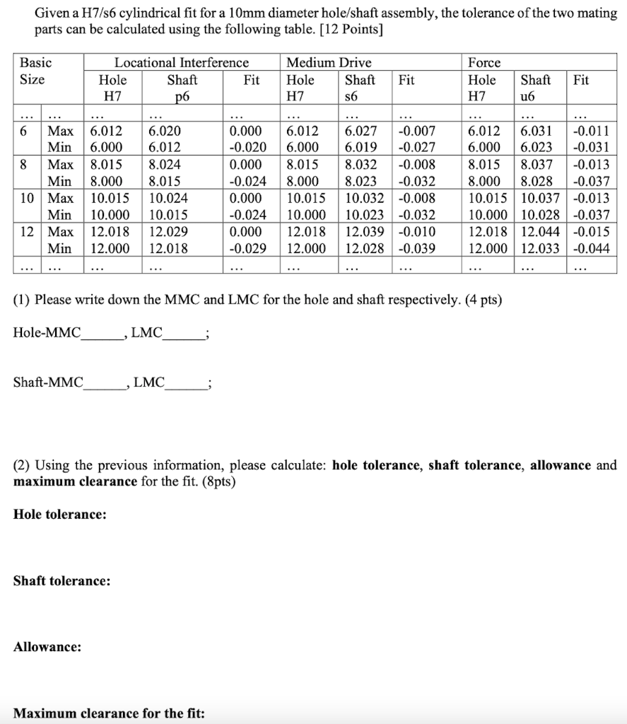
The H7 tolerance for a 10mm hole is a dimensional tolerance that specifies the allowed deviation from the nominal size of the hole. In this case, the H7 tolerance for a 10mm hole means that the actual size of the hole can vary between 9.92mm and 10.00mm. This tolerance zone is defined by the International Organization for Standardization (ISO) and is commonly used in engineering and manufacturing to ensure interchangeability and reliability of parts.
Understanding Tolerance Zones
The H7 tolerance zone is a unilateral tolerance zone, which means that the actual size of the hole can only deviate from the nominal size in one direction. In this case, the actual size of the hole can be smaller than the nominal size, but not larger. The tolerance zone is defined by the lower limit (9.92mm) and the upper limit (10.00mm) of the allowed deviation. Here are some key points to understand about tolerance zones:
- The tolerance zone is the range of allowed deviations from the nominal size.
- The lower limit is the smallest allowed size of the hole (9.92mm).
- The upper limit is the largest allowed size of the hole (10.00mm).
Importance of Tolerances in Engineering
Tolerances are crucial in engineering and manufacturing because they ensure that parts are interchangeable and reliable. Without tolerances, parts may not fit together properly, which can lead to component failure and system malfunction. The H7 tolerance for a 10mm hole is an example of how tolerances can be used to ensure that parts are manufactured to precise specifications. Here are some key points to understand about the importance of tolerances:
- Tolerances ensure that parts are interchangeable and reliable.
- Tolerances prevent component failure and system malfunction.
- Tolerances are essential in engineering and manufacturing to ensure precise specifications.
Tolerance Classification
The H7 tolerance is classified as a medium tolerance zone, which means that it allows for a moderate amount of deviation from the nominal size. There are several other tolerance zones that are classified as fine, medium, or coarse, depending on the allowed deviation. Here are some key points to understand about tolerance classification:
- The H7 tolerance is classified as a medium tolerance zone.
- Fine tolerances allow for small deviations from the nominal size.
- Coarse tolerances allow for large deviations from the nominal size.
Calculating Tolerances
Calculating tolerances involves determining the allowed deviation from the nominal size based on the tolerance zone and the nominal size. In the case of the H7 tolerance for a 10mm hole, the lower limit and upper limit of the allowed deviation are calculated based on the nominal size and the tolerance zone. Here are some key points to understand about calculating tolerances:
- Calculating tolerances involves determining the allowed deviation from the nominal size.
- The lower limit and upper limit of the allowed deviation are calculated based on the nominal size and the tolerance zone.
- Tolerance calculations require careful consideration of dimensional tolerances and geometric tolerances.
Applications of Tolerances
Tolerances have a wide range of applications in engineering and manufacturing, including mechanical engineering, aerospace engineering, and automotive engineering. The H7 tolerance for a 10mm hole is an example of how tolerances can be used to ensure precise specifications in mechanical engineering. Here are some key points to understand about the applications of tolerances:
- Tolerances have a wide range of applications in engineering and manufacturing.
- Mechanical engineering relies heavily on tolerances to ensure precise specifications.
- Aerospace engineering and automotive engineering also rely on tolerances to ensure reliability and safety.
What is the formula for calculating tolerance?
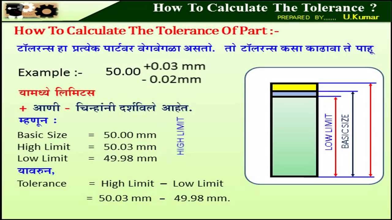
The formula for calculating tolerance is a mathematical expression that represents the acceptable limit of variation in a physical dimension or a statistical parameter. It is typically represented as a range of values within which a measurement or a parameter is considered to be acceptable. The formula for calculating tolerance is: tolerance = (upper limit - lower limit) / 2, where the upper limit and lower limit are the maximum and minimum acceptable values of the parameter or dimension.
Understanding Tolerance Calculation
The calculation of tolerance is crucial in various fields such as engineering, manufacturing, and quality control. To calculate tolerance, one needs to understand the concept of variability and uncertainty in measurements. The following steps are involved in calculating tolerance:
- Identify the parameter or dimension for which the tolerance needs to be calculated
- Determine the upper limit and lower limit of the acceptable range of values
- Calculate the tolerance using the formula: tolerance = (upper limit - lower limit) / 2
Tolerance Calculation in Engineering
In engineering, tolerance calculation is critical to ensure that the designed components or systems meet the required specifications. The calculation of tolerance involves understanding the material properties, manufacturing processes, and assembly requirements. The following factors are considered when calculating tolerance in engineering:
- Material properties such as strength, stiffness, and density
- Manufacturing processes such as machining, casting, and molding
- Assembly requirements such as fit, clearance, and interference
Statistical Tolerance Calculation
Statistical tolerance calculation involves using statistical methods to determine the tolerance of a parameter or dimension. This approach is used when there is uncertainty or variability in the measurements. The following steps are involved in statistical tolerance calculation:
- Collect data on the parameter or dimension of interest
- Analyze the data using statistical methods such as regression and confidence intervals
- Calculate the tolerance using statistical formulas such as the standard deviation and variance
Importance of Tolerance Calculation
The calculation of tolerance is essential in various fields to ensure that the products or systems meet the required specifications. The importance of tolerance calculation can be seen in the following aspects:
- Quality control: Tolerance calculation helps to ensure that the products meet the required quality standards
- Safety: Tolerance calculation helps to ensure that the products or systems are safe for use
- Reliability: Tolerance calculation helps to ensure that the products or systems are reliable and durable
Challenges in Tolerance Calculation
There are several challenges involved in calculating tolerance, including:
- Uncertainty: Uncertainty in measurements and variability in parameters or dimensions can make it difficult to calculate tolerance
- Complexity: Complex systems or components can make it challenging to calculate tolerance
- Lack of data: Lack of data or inadequate data can make it difficult to calculate tolerance
Frequently Asked Questions (FAQs)
What is the purpose of the Table of Metric Hole Tolerances per ISO 286 Chart Calculator?
The Table of Metric Hole Tolerances per ISO 286 Chart Calculator is a tool used to determine the tolerances and limits of metric holes according to the ISO 286 standard. This standard provides a set of rules for calculating the tolerances and limits of holes and shafts to ensure that they fit together properly and function as intended. The calculator is used to calculate the upper and lower limits of the hole diameter, as well as the fundamental deviation and tolerance zone, which are all critical parameters in the design and manufacture of mechanical components. By using the Table of Metric Hole Tolerances per ISO 286 Chart Calculator, engineers and designers can ensure that their designs meet the required standards and specifications, and that the components they produce are interchangeable and reliable.
How does the Table of Metric Hole Tolerances per ISO 286 Chart Calculator work?
The Table of Metric Hole Tolerances per ISO 286 Chart Calculator works by using a set of formulas and tables to calculate the tolerances and limits of metric holes. The calculator takes into account the nominal diameter of the hole, as well as the tolerance class and fundamental deviation, to determine the upper and lower limits of the hole diameter. The calculator also uses the ISO 286 standard to determine the tolerance zone, which is the range of sizes within which the hole must fall to meet the required standards. By using the calculator, users can quickly and easily determine the tolerances and limits of metric holes, without having to manually calculate the values using complex formulas. This makes it an essential tool for engineers and designers who work with mechanical components and need to ensure that their designs meet the required standards and specifications.
What are the benefits of using the Table of Metric Hole Tolerances per ISO 286 Chart Calculator?
The benefits of using the Table of Metric Hole Tolerances per ISO 286 Chart Calculator are numerous. Firstly, it saves time and reduces error, as users do not have to manually calculate the tolerances and limits of metric holes using complex formulas. Secondly, it ensures accuracy, as the calculator uses precise formulas and tables to determine the tolerances and limits of metric holes. Thirdly, it improves reliability, as users can be confident that their designs meet the required standards and specifications, and that the components they produce are interchangeable and reliable. Finally, it reduces costs, as users can avoid the costs associated with rework and scrap, and can produce high-quality components that meet the required standards and specifications. By using the Table of Metric Hole Tolerances per ISO 286 Chart Calculator, users can streamline their design process, improve their productivity, and produce high-quality components that meet the required standards and specifications.
Who can benefit from using the Table of Metric Hole Tolerances per ISO 286 Chart Calculator?
The Table of Metric Hole Tolerances per ISO 286 Chart Calculator can benefit a wide range of professionals, including engineers, designers, manufacturers, and quality control specialists. Engineers and designers can use the calculator to design and develop mechanical components that meet the required standards and specifications. Manufacturers can use the calculator to produce high-quality components that are interchangeable and reliable. Quality control specialists can use the calculator to inspect and test components to ensure that they meet the required standards and specifications. Additionally, students and researchers can use the calculator to learn about tolerances and limits of metric holes, and to conduct research on mechanical components. By using the Table of Metric Hole Tolerances per ISO 286 Chart Calculator, professionals can improve their productivity, reduce errors, and produce high-quality components that meet the required standards and specifications.
Deja una respuesta
Entradas Relacionadas