
Preferred Tolerances Inch Units Chart ANSI B4.1 Calculator RC - LT Fits

The Preferred Tolerances Inch Units Chart ANSI B4.1 Calculator RC - LT Fits is a crucial tool in engineering and manufacturing. It provides a standardized system for calculating tolerances and fits in inch units, ensuring precision and consistency in the design and production of mechanical components. By using this calculator, engineers and manufacturers can determine the optimal tolerances and fits for their specific applications, adhering to the American National Standards Institute (ANSI) B4.1 guidelines. This facilitates efficient and accurate production, reducing errors and improving overall product quality and reliability. The calculator is widely used in various industries.
- Understanding Preferred Tolerances Inch Units Chart ANSI B4.1 Calculator RC - LT Fits
- What is ANSI B4 1?
- How do you calculate fits and tolerances?
- What is the allowance for a shaft measuring 1 inch in diameter with an RC6 sliding fit?
- What is the tolerance of a standard clearance fit?
-
Frequently Asked Questions (FAQs)
- What is the purpose of the Preferred Tolerances Inch Units Chart ANSI B4.1 Calculator RC - LT Fits?
- How does the Preferred Tolerances Inch Units Chart ANSI B4.1 Calculator RC - LT Fits work?
- What are the benefits of using the Preferred Tolerances Inch Units Chart ANSI B4.1 Calculator RC - LT Fits?
- Can the Preferred Tolerances Inch Units Chart ANSI B4.1 Calculator RC - LT Fits be used in various industries?
Understanding Preferred Tolerances Inch Units Chart ANSI B4.1 Calculator RC - LT Fits
The Preferred Tolerances Inch Units Chart ANSI B4.1 Calculator RC - LT Fits is a standard used in engineering and manufacturing to determine the tolerances and fits of mechanical parts. This standard provides a set of preferred tolerances and fits for inch units, which are widely used in the United States and other countries. The calculator is used to determine the recommended clearance and interference fits for various applications.
Introduction to ANSI B4.1 Standard
The ANSI B4.1 standard is a widely accepted industry standard that provides guidelines for dimensioning and tolerancing of mechanical parts. The standard covers the basic dimensions, tolerances, and fits for various types of parts, including shafts and holes. The standard is used to ensure interchangeability and compatibility of parts, which is critical in modern manufacturing.
Understanding RC and LT Fits
RC and LT fits are two types of fits that are commonly used in mechanical design. RC fits are used for running clearance applications, where a small amount of clearance is required between the shaft and hole. LT fits, on the other hand, are used for loose transition applications, where a larger amount of clearance is required. The calculator is used to determine the recommended RC and LT fits for various applications.
Preferred Tolerances Inch Units Chart
The Preferred Tolerances Inch Units Chart is a table that lists the preferred tolerances for inch units. The chart provides a range of tolerances for various basic dimensions, from 0.01 to 10 inches. The chart is used to determine the recommended tolerance for a given basic dimension.
| Basic Dimension | Preferred Tolerance |
|---|---|
| 0.01-0.1 | +0.001 / -0.001 |
| 0.1-1.0 | +0.005 / -0.005 |
| 1.0-10.0 | +0.01 / -0.01 |
Calculator for RC - LT Fits
The calculator for RC - LT fits is a tool used to determine the recommended clearance and interference fits for various applications. The calculator takes into account the basic dimension, tolerance, and fit type to determine the recommended clearance or interference.
Applications of Preferred Tolerances Inch Units Chart ANSI B4.1 Calculator RC - LT Fits
The Preferred Tolerances Inch Units Chart ANSI B4.1 Calculator RC - LT Fits has a wide range of applications in engineering and manufacturing. The standard is used in the design and production of mechanical parts, including shafts, holes, and gears. The standard is also used in quality control and inspection to ensure interchangeability and compatibility of parts. Manufacturers use the standard to ensure that their products meet the required specifications and industry standards.
What is ANSI B4 1?

ANSI B4.1 is a standard for dimensional tolerancing and geometric tolerancing in the United States. It provides a set of rules and guidelines for specifying and interpreting tolerances and limits on engineering drawings and computer-aided design (CAD) models. The standard is published by the American National Standards Institute (ANSI) and is widely used in the manufacturing industry to ensure interchangeability and compatibility of parts and assemblies.
Introduction to ANSI B4.1
ANSI B4.1 is a critical standard in the engineering and manufacturing fields, as it provides a common language for specifying and interpreting tolerances and limits. The standard includes rules for dimensional tolerancing, geometric tolerancing, and surface finish, among others. Some key aspects of ANSI B4.1 include:
- Tolerance zones: The standard defines tolerance zones as the range of values within which a dimension or geometric characteristic must fall.
- Tolerance types: ANSI B4.1 recognizes several types of tolerances, including unilateral, bilateral, and limit tolerances.
- Geometric tolerancing: The standard provides rules for specifying geometric tolerances, such as flatness, straightness, and circularity.
Benefits of Using ANSI B4.1
The use of ANSI B4.1 offers several benefits, including improved interchangeability and compatibility of parts and assemblies, reduced errors and misinterpretations, and increased efficiency in manufacturing and inspection. By providing a standard set of rules and guidelines for dimensional tolerancing and geometric tolerancing, ANSI B4.1 helps to minimize confusion and maximize clarity in engineering drawings and CAD models. Some key benefits of using ANSI B4.1 include:
- Improved communication: The standard provides a common language for engineers, designers, and manufacturers to communicate design intent and tolerance requirements.
- Increased accuracy: ANSI B4.1 helps to minimize errors and misinterpretations by providing clear and unambiguous rules for dimensional tolerancing and geometric tolerancing.
- Reduced costs: By reducing errors and improving efficiency, the use of ANSI B4.1 can help to lower costs and improve profitability in manufacturing and engineering applications.
Key Concepts in ANSI B4.1
ANSI B4.1 introduces several key concepts, including dimensional tolerancing, geometric tolerancing, and surface finish. The standard also recognizes several types of tolerances, including unilateral, bilateral, and limit tolerances. Some other key concepts in ANSI B4.1 include:
- Tolerance stackup: The standard provides rules for calculating tolerance stackup, which is the cumulative effect of tolerances on assembled parts.
- Geometric dimensioning and tolerancing (GD&T): ANSI B4.1 provides a framework for geometric dimensioning and tolerancing, which is a method of specifying geometric tolerances using symbols and notations.
- Certification and verification: The standard provides guidelines for certification and verification of parts and assemblies, including inspection and testing procedures.
Applications of ANSI B4.1
ANSI B4.1 has a wide range of applications in engineering and manufacturing, including aerospace, automotive, medical devices, and consumer products. The standard is used to specify tolerances and limits on engineering drawings and CAD models, and to ensure interchangeability and compatibility of parts and assemblies. Some other applications of ANSI B4.1 include:
- Mechanical engineering: The standard is widely used in mechanical engineering to specify tolerances and limits on mechanical components and assemblies.
- Quality control: ANSI B4.1 is used in quality control to ensure that parts and assemblies meet specified requirements and tolerances.
- Computer-aided design (CAD): The standard is used in CAD to specify tolerances and limits on digital models and to ensure interchangeability and compatibility of CAD data.
Future Developments in ANSI B4.1
The American National Standards Institute (ANSI) continually reviews and updates ANSI B4.1 to reflect advances in technology and changes in industry practices. Some potential future developments in ANSI B4.1 include:
- Integration with other standards: The standard may be integrated with other standards and specifications, such as ISO and ASME standards, to provide a more comprehensive framework for dimensional tolerancing and geometric tolerancing.
- New technologies and applications: ANSI B4.1 may be updated to include new technologies and applications, such as additive manufacturing and artificial intelligence.
- Improved usability and accessibility: The standard may be revised to improve usability and accessibility, including simplified language and enhanced graphics.
How do you calculate fits and tolerances?
To calculate fits and tolerances, you need to understand the basic concepts of dimensional tolerancing and geometric tolerancing. The calculation of fits and tolerances involves determining the allowed variation in the size of a part or feature to ensure that it can be assembled or function properly with other parts. The calculation typically involves the use of formulas and tables that provide the limits of size for the part or feature.
Understanding Fits and Tolerances
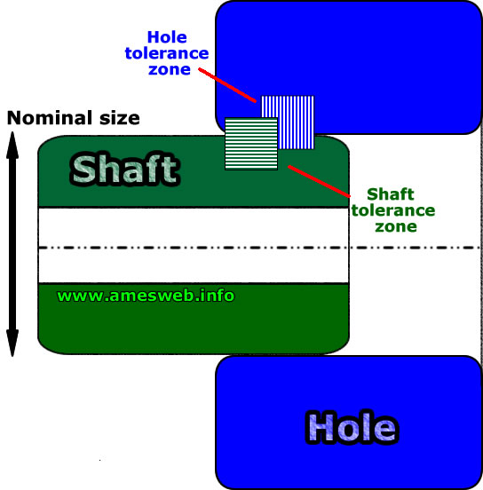
To calculate fits and tolerances, you need to understand the different types of fits, including clearance fits, transition fits, and interference fits. A clearance fit is a fit where the hole is larger than the shaft, while a transition fit is a fit where the hole and shaft are approximately the same size. An interference fit is a fit where the shaft is larger than the hole. The calculation of fits and tolerances for these different types of fits involves determining the maximum and minimum sizes of the hole and shaft.
- Clearance fits are used when a loose fit is required, such as in a bearing or piston.
- Transition fits are used when a moderate fit is required, such as in a gears or splines.
- Interference fits are used when a tight fit is required, such as in a press fit or shrink fit.
Calculating Tolerances
To calculate tolerances, you need to determine the nominal size of the part or feature, as well as the allowable variation in size. The tolerance is the difference between the maximum and minimum sizes of the part or feature. The calculation of tolerances involves the use of formulas, such as the tolerance formula, which takes into account the nominal size, tolerance grade, and tolerance position.
- Nominal size is the theoretical size of the part or feature.
- Allowable variation is the amount of variation in size that is allowed.
- Tolerance grade is the level of precision required for the part or feature.
Using Tolerance Tables
Tolerance tables provide a quick reference for determining the limits of size for a part or feature. These tables list the nominal size, tolerance grade, and tolerance position for a range of standard sizes. To use a tolerance table, you simply look up the nominal size and tolerance grade to determine the maximum and minimum sizes of the part or feature.
- Tolerance tables are published by standards organizations, such as the American Society of Mechanical Engineers (ASME).
- Standard sizes are established by industry standards, such as the Inch or Metric system.
- Tolerance grades are defined by standards organizations, such as the International Organization for Standardization (ISO).
Applying Geometric Tolerancing
Geometric tolerancing involves the use of symbols and notations to specify the requirements for the form, orientation, and location of a part or feature. The application of geometric tolerancing involves the use of GD&T (Geometric Dimensioning and Tolerancing), which provides a standardized method for specifying and interpreting geometric tolerances.
- GD&T is a standardized method for specifying geometric tolerances.
- Symbols and notations are used to! specify the requirements for the form, orientation, and location of a part or feature.
- Form tolerances are used to control the shape of a part or feature.
Verifying Fits and Tolerances
To verify fits and tolerances, you need to measure the size of the part or feature and compare it to the specified tolerances. The verification of fits and tolerances involves the use of measurement instruments, such as calipers or micrometers, to determine the actual size of the part or feature.
- Measurement instruments are used to measure the size of the part or feature.
- Calipers are used to measure the diameter or width of a part or feature.
- Micrometers are used to measure the diameter or thickness of a part or feature.
What is the allowance for a shaft measuring 1 inch in diameter with an RC6 sliding fit?
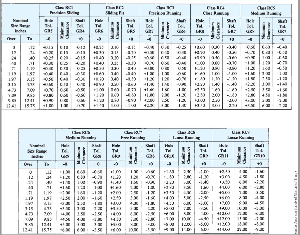
The allowance for a shaft measuring 1 inch in diameter with an RC6 sliding fit can be determined by referring to the ANSI B4.2 standard, which provides guidelines for tolerances and allowances for shaft and hole combinations. For an RC6 sliding fit, the shaft diameter is typically smaller than the hole diameter, with a specific allowance to ensure smooth movement.
Understanding RC6 Sliding Fit
The RC6 sliding fit is a type of fit that allows for smooth movement between the shaft and the hole. This fit is commonly used in applications where precision and low friction are required. The allowance for an RC6 sliding fit is typically 0.0015 inches for a 1-inch diameter shaft. Here are the key characteristics of an RC6 sliding fit:
- The shaft diameter is smaller than the hole diameter by a specific allowance.
- The allowance is designed to provide a smooth, sliding fit between the shaft and the hole.
- The RC6 sliding fit is suitable for applications where low friction and precision are required.
Factors Affecting Allowance
Several factors can affect the allowance for a shaft measuring 1 inch in diameter with an RC6 sliding fit. These include the material of the shaft and hole, the surface finish, and the operating conditions. For example, a shaft made of steel may require a different allowance than a shaft made of aluminum. Here are some key factors to consider:
- The material of the shaft and hole can affect the allowance.
- The surface finish of the shaft and hole can also impact the allowance.
- The operating conditions, such as temperature and humidity, can influence the allowance.
Calculating Allowance
To calculate the allowance for a shaft measuring 1 inch in diameter with an RC6 sliding fit, you can use the ANSI B4.2 standard as a reference. The standard provides tolerance and allowance values for different fits, including the RC6 sliding fit. Here are the steps to calculate the allowance:
- Refer to the ANSI B4.2 standard for the tolerance and allowance values for an RC6 sliding fit.
- Look up the allowance value for a 1-inch diameter shaft with an RC6 sliding fit.
- Adjust the allowance value based on the factors that affect the allowance, such as material and surface finish.
Importance of Allowance
The allowance is a critical factor in determining the fit between a shaft and a hole. A proper allowance can ensure smooth movement, low friction, and longer life for the shaft and hole. Here are the benefits of a proper allowance:
- A proper allowance can ensure smooth movement between the shaft and the hole.
- A proper allowance can reduce friction and wear on the shaft and hole.
- A proper allowance can extend the life of the shaft and hole.
Common Applications
The RC6 sliding fit is commonly used in applications where precision and low friction are required. Some examples of common applications include bearings, gears, and pulleys. Here are some key characteristics of these applications:
- Bearings require a smooth and low-friction fit to ensure long life and reliable operation.
- Gears require a precise fit to ensure smooth movement and efficient power transmission.
- Pulleys require a sliding fit to ensure smooth movement and low friction.
What is the tolerance of a standard clearance fit?

The tolerance of a standard clearance fit is the amount of variation allowed between the shaft and the hole. In a clearance fit, the shaft is smaller than the hole, and the tolerance determines the range of acceptable clearance values. A standard clearance fit typically has a loose tolerance, which allows for some movement and play between the shaft and the hole.
Definition of Clearance Fit
A clearance fit is a type of fit where the shaft is smaller than the hole, and it is used when movement or rotation is required. The tolerance of a clearance fit is typically loose, which allows for some play between the shaft and the hole. Some key points about clearance fits include:
- The shaft is smaller than the hole.
- The fit is used for movement or rotation.
- The tolerance is typically loose.
Types of Clearance Fits
There are several types of clearance fits, including loose, free, and slip fits. Each type of fit has a different tolerance range, and the choice of fit depends on the application and the required movement or rotation. Some key points about the different types of clearance fits include:
- Loose fits have a large clearance and are used for low-precision applications.
- Free fits have a medium clearance and are used for general-purpose applications.
- Slip fits have a small clearance and are used for high-precision applications.
Factors Affecting Clearance Fit Tolerance
The tolerance of a clearance fit is affected by several factors, including the material of the shaft and the hole, the surface finish, and the temperature. The material of the shaft and the hole can affect the thermal expansion and the wear of the fit. Some key points about the factors affecting clearance fit tolerance include:
- The material of the shaft and the hole can affect the thermal expansion.
- The surface finish can affect the wear of the fit.
- The temperature can affect the clearance value.
Calculating Clearance Fit Tolerance
The tolerance of a clearance fit can be calculated using formulas and tables. The calculation takes into account the basic size of the shaft and the hole, as well as the tolerance range. Some key points about calculating clearance fit tolerance include:
- The basic size of the shaft and the hole must be known.
- The tolerance range must be specified.
- Formulas and tables can be used to calculate the tolerance.
Applications of Clearance Fits
Clearance fits are used in a variety of applications, including mechanical systems, electrical systems, and aerospace systems. The tolerance of the clearance fit depends on the application and the required movement or rotation. Some key points about the applications of clearance fits include:
- Mechanical systems use clearance fits for movement and rotation.
- Electrical systems use clearance fits for connectors and switches.
- Aerospace systems use clearance fits for high-precision applications.
Frequently Asked Questions (FAQs)
What is the purpose of the Preferred Tolerances Inch Units Chart ANSI B4.1 Calculator RC - LT Fits?
The Preferred Tolerances Inch Units Chart ANSI B4.1 Calculator RC - LT Fits is a tool designed to help engineers and manufacturers determine the optimal tolerances and fits for their products. The ANSI B4.1 standard provides a set of guidelines for calculating preferred tolerances and fits in inch units, which is essential for ensuring the interchangeability and compatibility of parts. By using this calculator, users can quickly and easily determine the maximum and minimum limits of size for a given tolerance and fit, which is crucial for ensuring the quality and reliability of the final product. Additionally, the RC - LT Fits calculator allows users to calculate the clearance and interference fits between two parts, which is essential for ensuring smooth and efficient assembly and operation.
How does the Preferred Tolerances Inch Units Chart ANSI B4.1 Calculator RC - LT Fits work?
The Preferred Tolerances Inch Units Chart ANSI B4.1 Calculator RC - LT Fits works by using a set of complex algorithms and formulas to calculate the optimal tolerances and fits for a given application. The calculator takes into account various factors, such as the material, manufacturing process, and desired level of precision, to determine the best possible tolerances and fits. The user simply inputs the required information, such as the tolerance and fit type, and the calculator provides the results in a clear and concise format. The calculator also provides graphs and charts to help users visualize the relationships between tolerances, fits, and clearance, making it easier to understand and apply the concepts.
What are the benefits of using the Preferred Tolerances Inch Units Chart ANSI B4.1 Calculator RC - LT Fits?
The Preferred Tolerances Inch Units Chart ANSI B4.1 Calculator RC - LT Fits offers several benefits to users, including increased accuracy and precision in calculating tolerances and fits. By using this calculator, users can reduce the risk of errors and mismatches, which can lead to costly rework and delays. Additionally, the calculator helps users to optimize their designs and manufacturing processes, which can lead to improved quality, reliability, and efficiency. The calculator also saves time and effort, as users do not have to manually calculate tolerances and fits using complex formulas and tables. Furthermore, the calculator provides standardized results, which can be easily communicated and shared with others, ensuring consistency and compliance with industry standards.
Can the Preferred Tolerances Inch Units Chart ANSI B4.1 Calculator RC - LT Fits be used in various industries?
The Preferred Tolerances Inch Units Chart ANSI B4.1 Calculator RC - LT Fits is a versatile tool that can be used in a wide range of industries, including aerospace, automotive, medical, and manufacturing. The calculator is particularly useful in industries where precision and accuracy are critical, such as in the production of aircraft and medical devices. Additionally, the calculator can be used in research and development, where prototypes and test parts need to be designed and manufactured with high precision. The calculator is also useful for students and educators, as it provides a convenient and intuitive way to learn about tolerances and fits, and to practice calculating them using real-world examples. Overall, the Preferred Tolerances Inch Units Chart ANSI B4.1 Calculator RC - LT Fits is a powerful tool that can be used by anyone who needs to calculate tolerances and fits with high accuracy and precision.
Deja una respuesta
Entradas Relacionadas